beegraphy.com.
BeeGraphy is an innovative cloud-based platform tailored for computational designers. It provides effortless cross-platform compatibility, removing the requirement for installations, thereby facilitating seamless usage on Windows, Mac, or Linux systems. By enabling model creation directly in the cloud and allowing easy sharing through a straightforward URL link, BeeGraphy fosters real-time collaboration and co-creation among individuals and teams. Beegraphy ensures that you can share your parametric models securely without disclosing the underlying script, empowering to present designs confidently. Additionally, Beegrapgy offers the opportunity to showcase and market models in Beegraphy online store, generating passive income.
For those familiar with Grasshopper, Beegraphy is very easy to master. Components are very similar and the inner logic remains the same. Beegraphy just seems to be a bit less powerful or flexible, especially with lists and has some minor issues with the 3D viewing space.
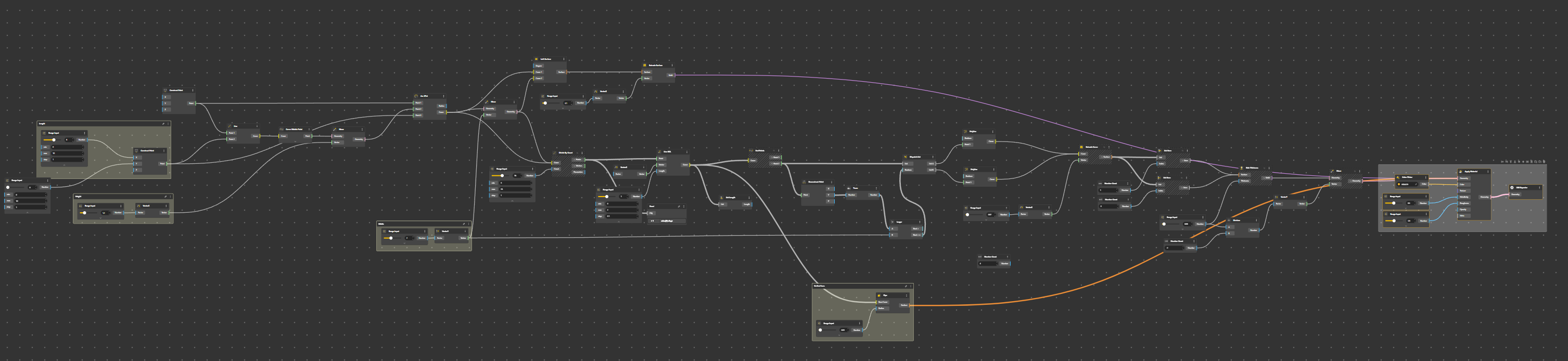
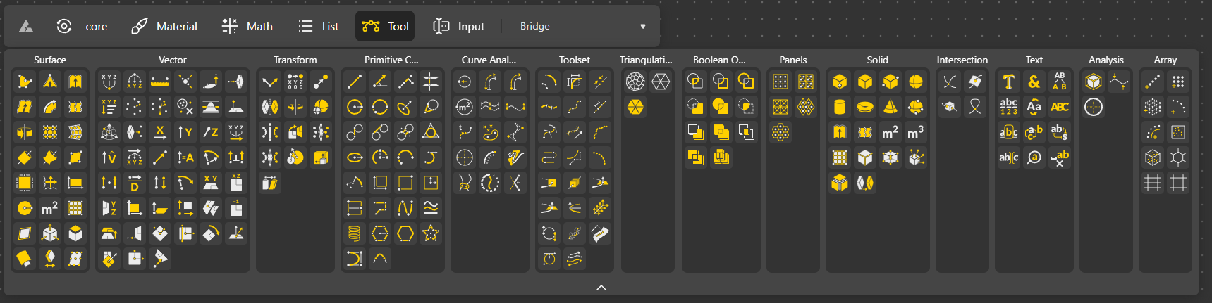
Tools are as shown below.
Bridge
We will test Beegraphy with a basic example that is deployed with Grasshopper here: http://www.keris-studio.fr/blog/?p=12883. Starting from a point, we will be able to create a simple parametric geometry.
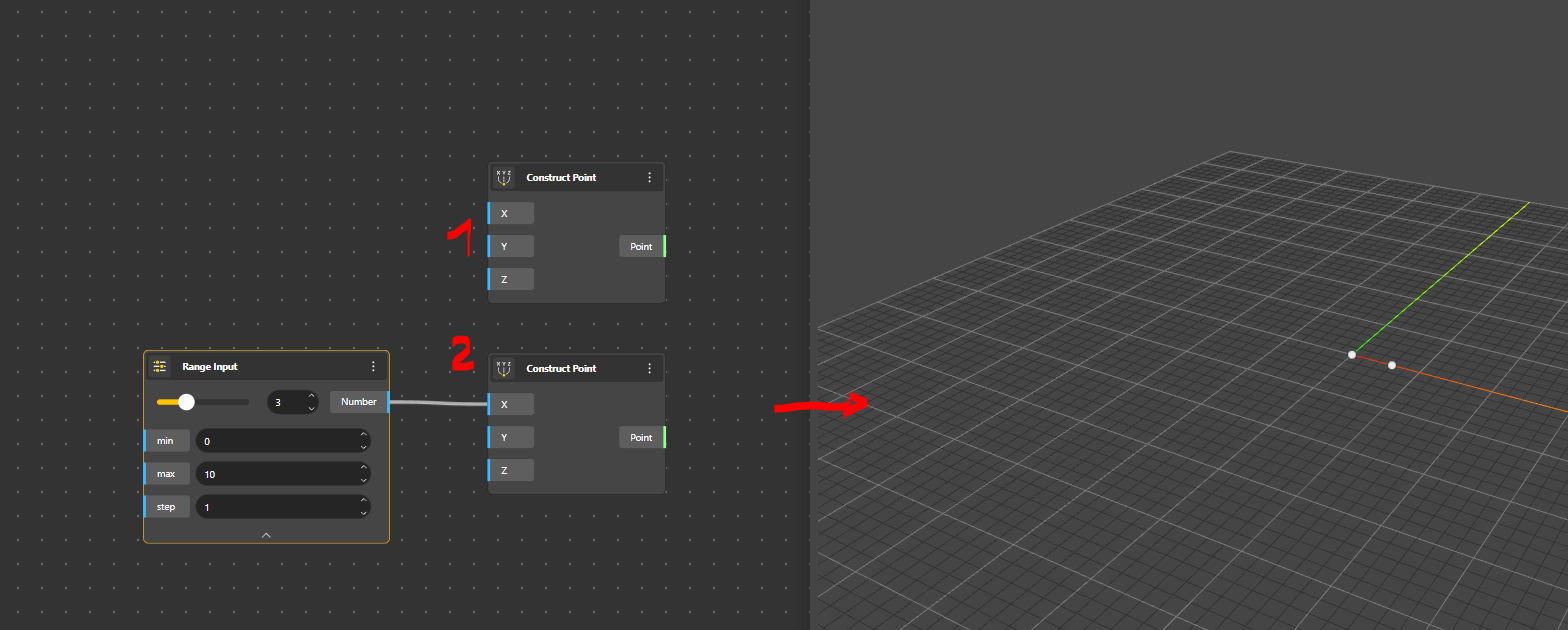
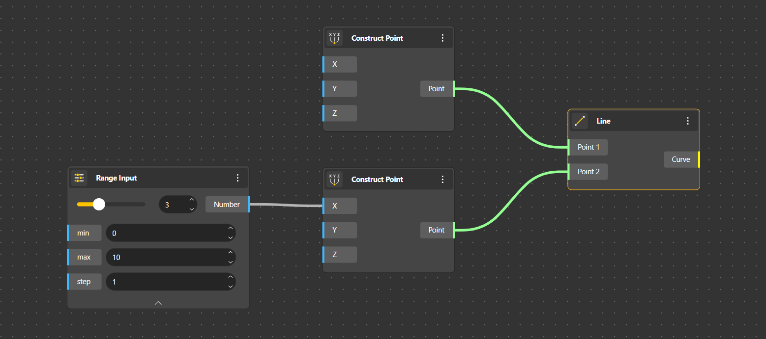
We start with a Control Point. Pretty much like in Grasshopper (and common geometry), a Control Point is referenced with 3 coordinates. We create a second one equipped with a Slider, which is called in Beegraphy Range Input. This value will give the length of the bridge.
We then create a Line by joining those 2 points.
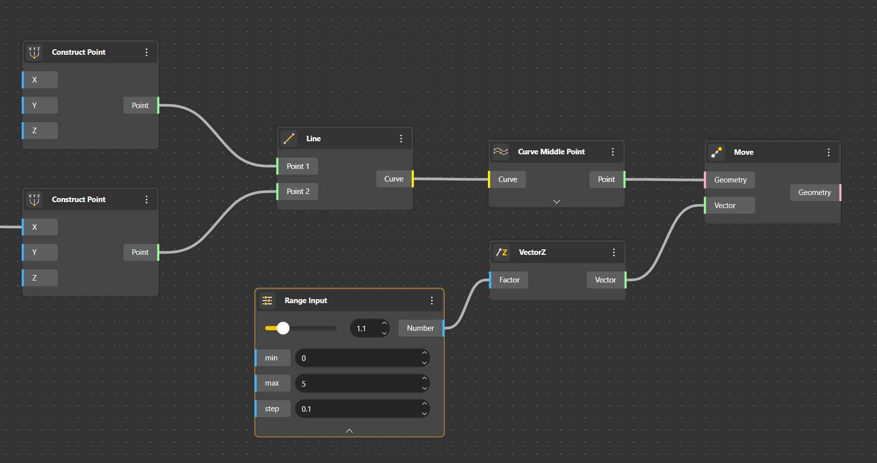
As we want to create a Curved bridge, we seek for the middle point. For that we use Curve Middle Point. That way, whatever the length will be, we will always have the middle point location. We then raise this middle point with the Move component. We indicate Vector Z and a value with the Range Input.
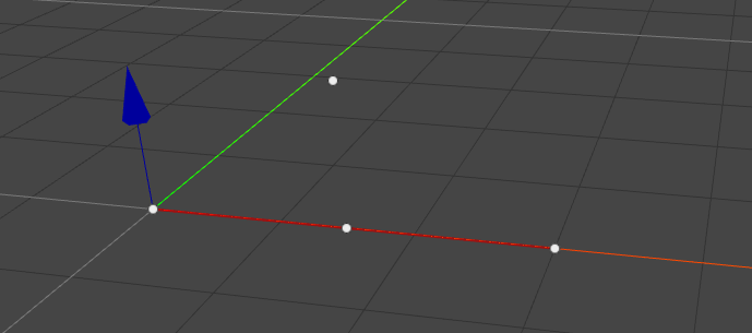
The midpoint is elevated.
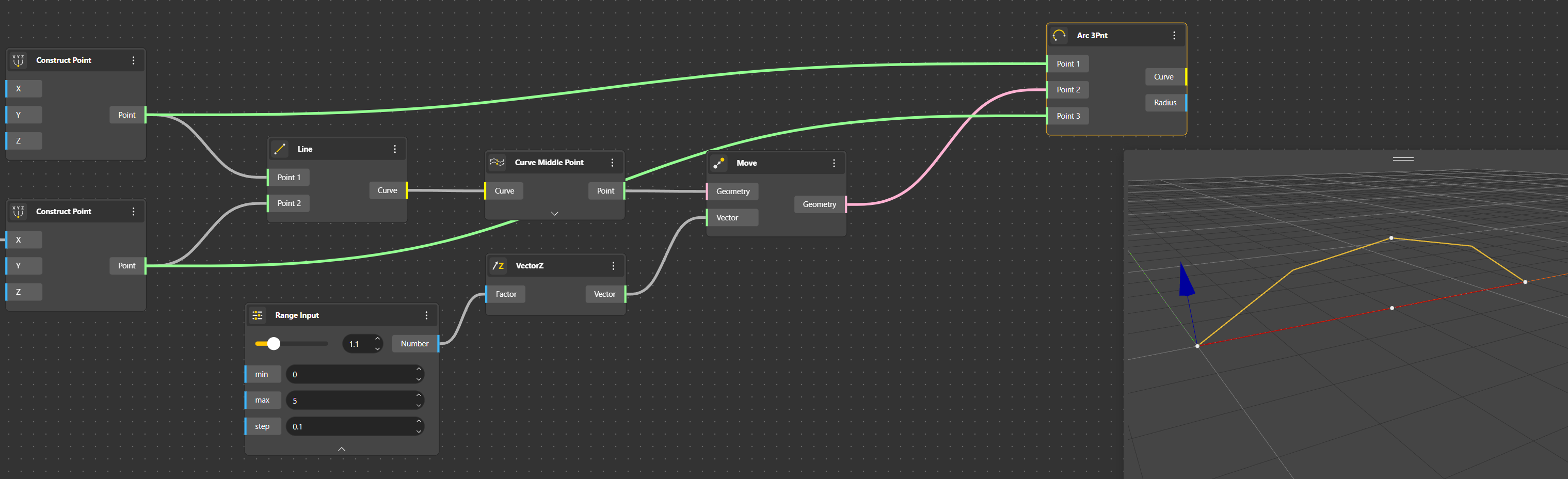
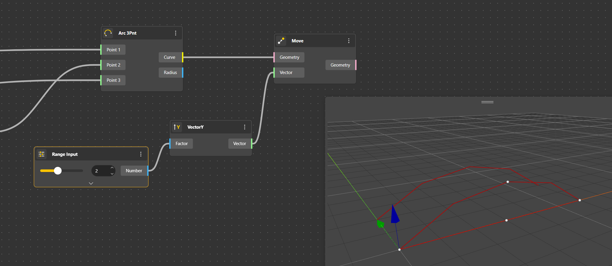
We can then use an Arc 3points to make the arch.
Then we duplicate with Move the arc line to have the width of the bridge. This width is also given with a Range Input and a Vector Y.
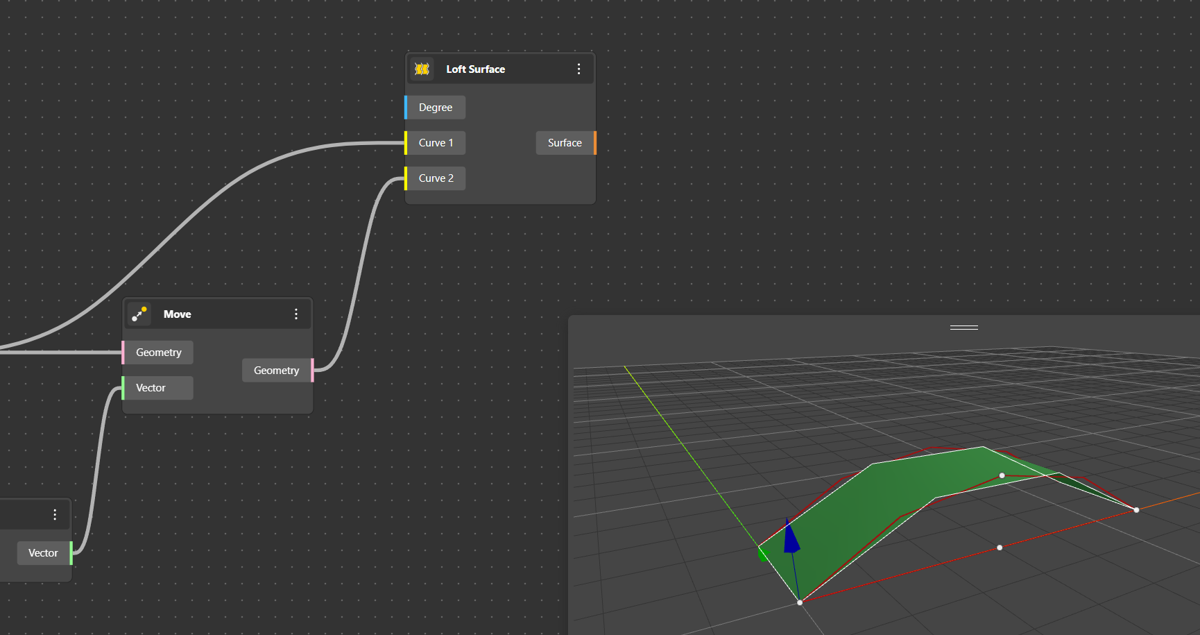
With a Loft Surface we can create a surface between the 2 curves. Even if I put the geometry resolution at the highest, it’s still very angular. I don’t know why.
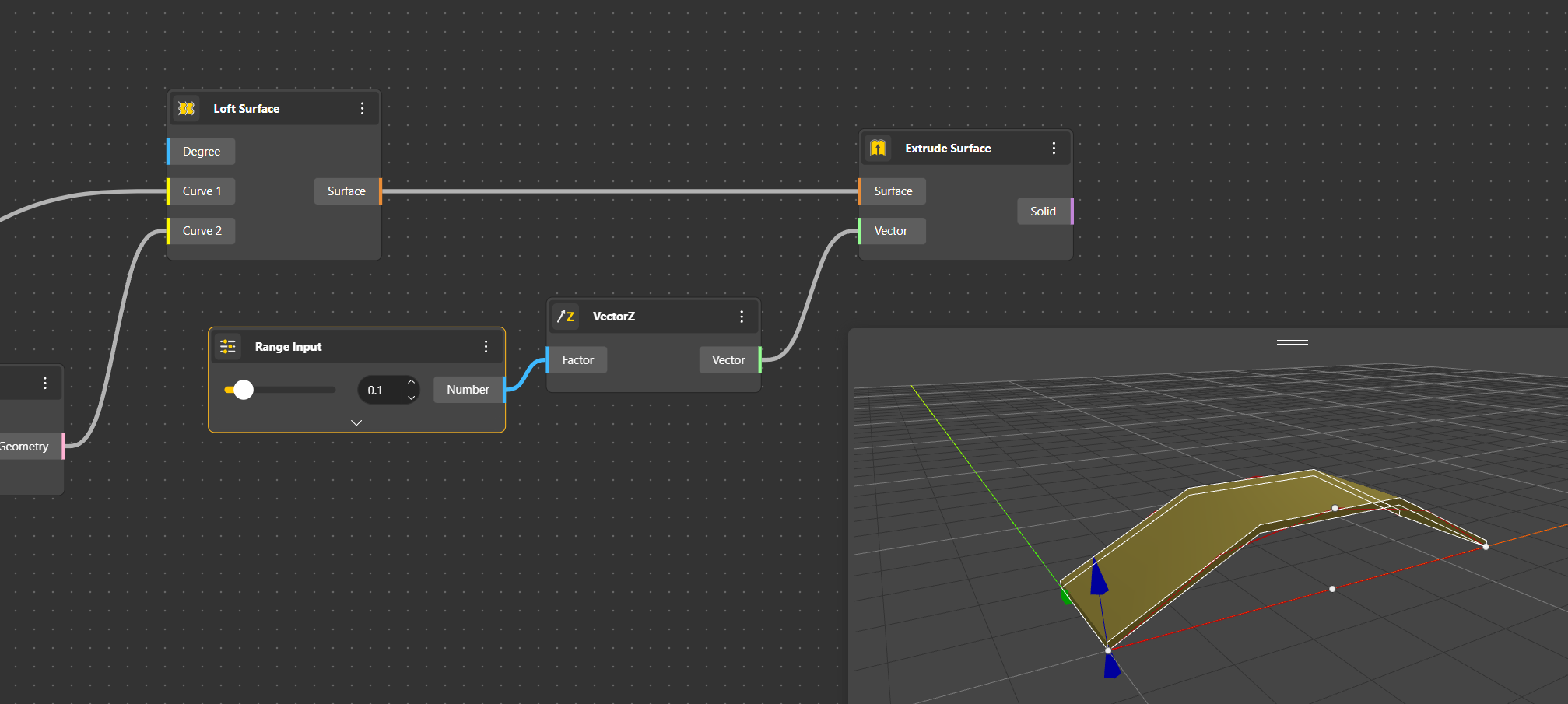
To have a volume instead of a simple surface, we can use Extrude Surface. Vector Z for the up direction and a Range Input to modify the thickness.
Getting thick
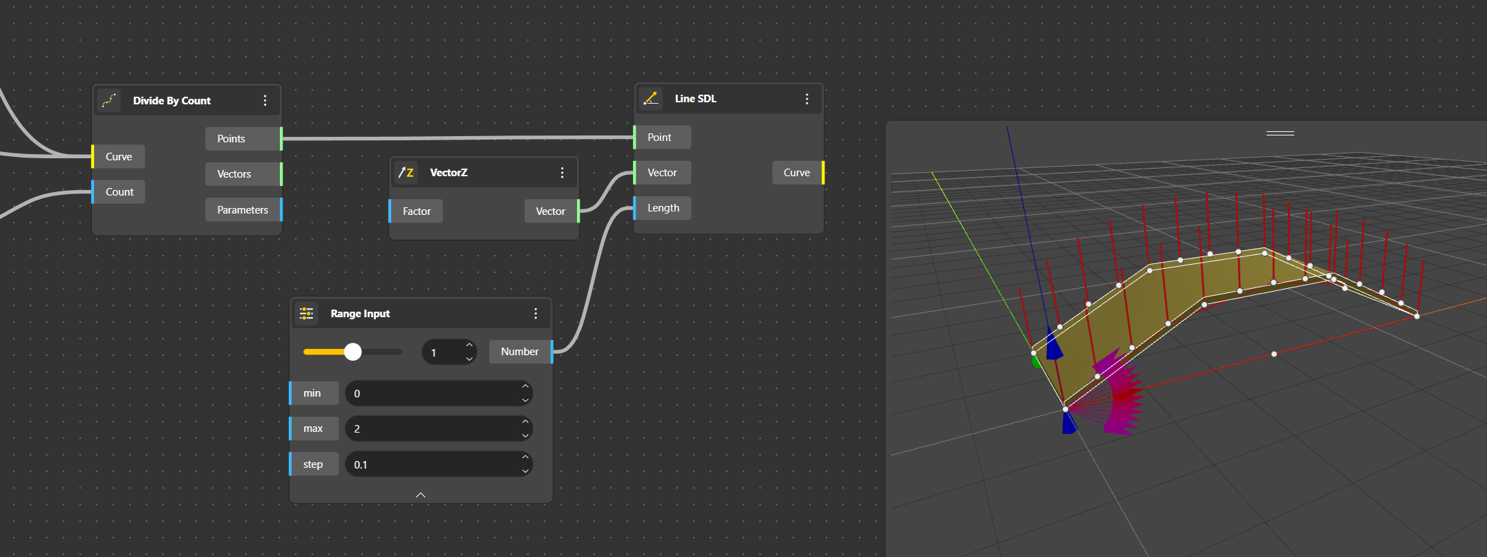
Ok, now it time to create the railings. We start from the arc, and to make things easier for now, we simply divide this arc into segments. For that we use Divide by Count and a Range Input (from 3 to 24 in this example).
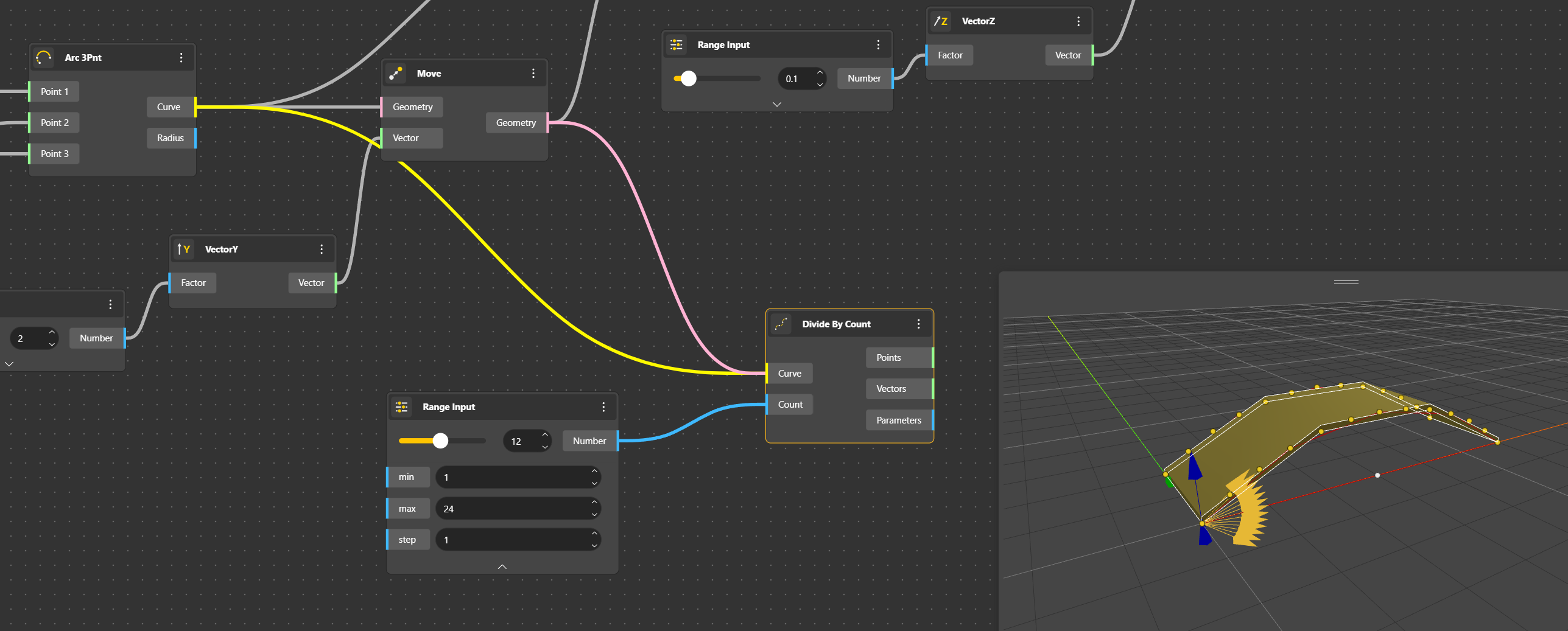
Then we use a Line SDL to create the vertical bars. A Vector Z tells that the lines have to go straight up and a Range Input let the possibility to modify the bars’ length.
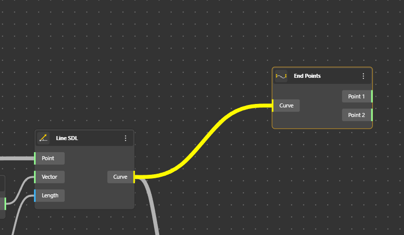
The handrail is done with a Curve. First it’s needed to get the End Points of each vertical bar.
Ok, at this stage we must have a break.
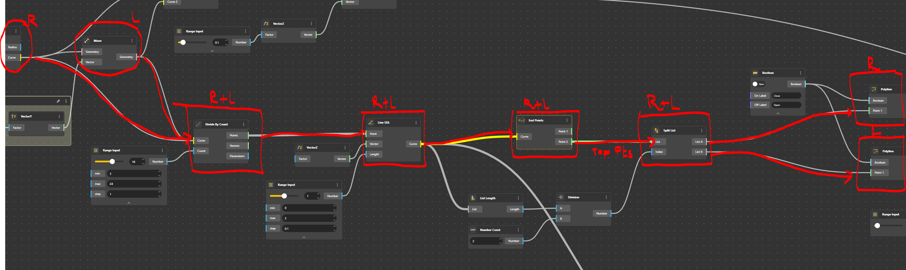
We connected the two arcs to the Divide Line component in order to go faster. All SDL lines are then created from the right arc and the left arc. For those familiar to Grasshopper, it means that we’ve got one list with two sub lists (branches) in the same component. Last recall that parametric design is all about lists and mastering it is quite the only issue.
To play with the lists, we will then split the lists, one for the right handrail and one for the left one. Why that? Well, it is faster to process this way, but we could have 2 parallel processes one for the right side and one for the left one. Let’s see that in the definition R is right side, L is Left side.
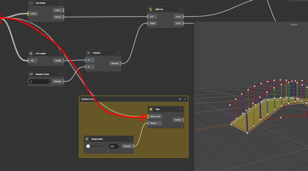
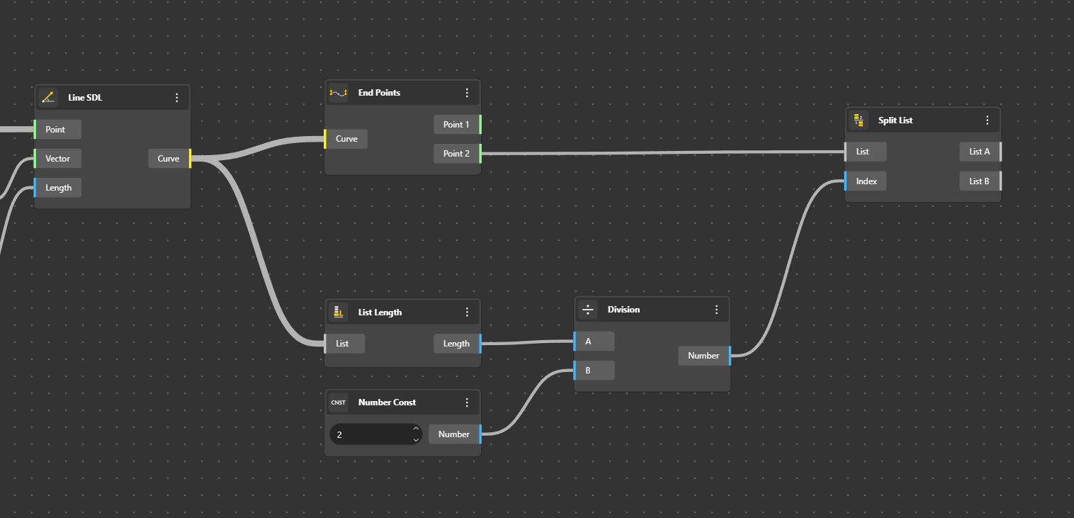
Before splitting the list, we use End Points to collect all end points from a segment, in our case, the vertical bars.
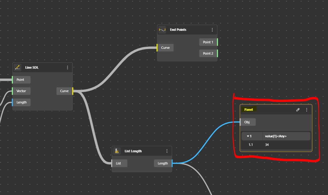
We try to see the length off our list to know where to cut (split) with the List Length component. We can use a Panel to visualise the result. Grasshopper users love panels. The length is a value so we can use it as a number that we divide by 2 and hop, we know where to cut. We use Number Count to input a number, Division to calculate and Split List to split.
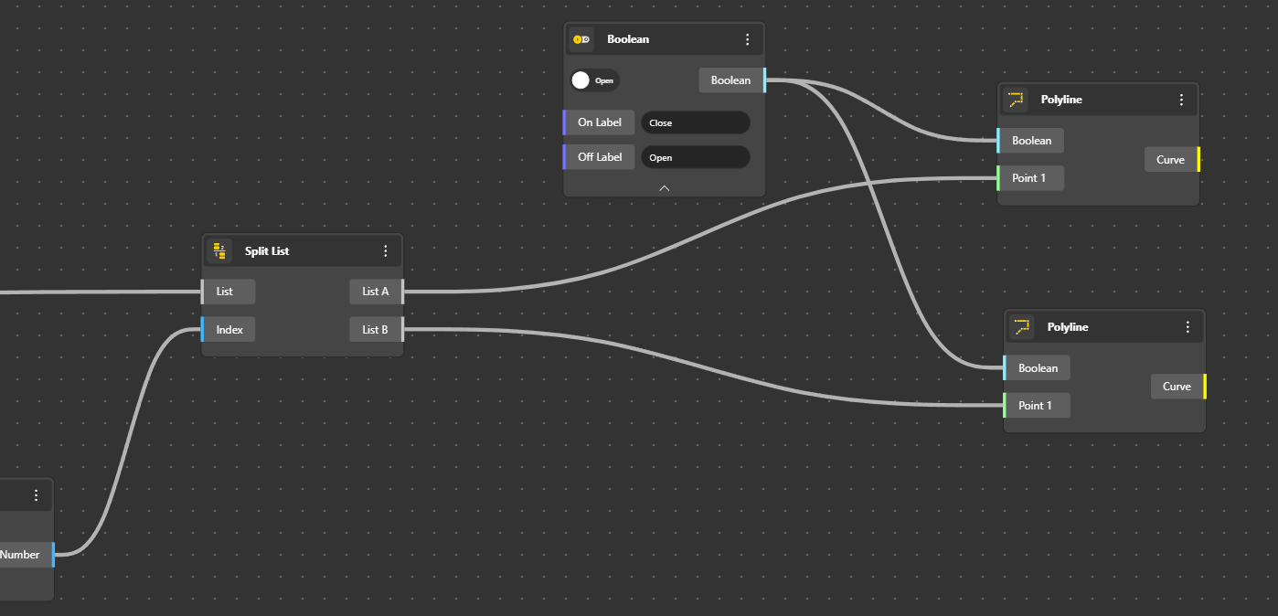
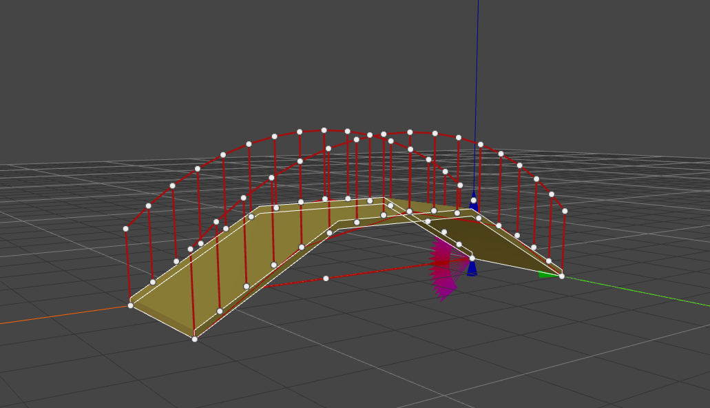
Ok, now have our points on the Right side and on The Left side. We can join them with a Polyline.
Ok now we’ve got our two handrails. We are ready to give some thickness to it.
Alternative
Ok at this stage I had an issue with the following steps. The other solution is to use a dispatch with a Boolean.
To dispatch I chose the Y distance which is also the width of my bridge. Points on the left side are separated from points of the Right side by their Y coordinates. To do so, we can use a Deconstruct Point to have the XYZ coordinates (I optionally trunked the number in order to have an integer) (Trunc). Then we can introduce the Boolean Larger and chose Larger or Equal to the width of the bridge. The bolean result is input to the Dispatch List. Then each list is connected to the Polyline.
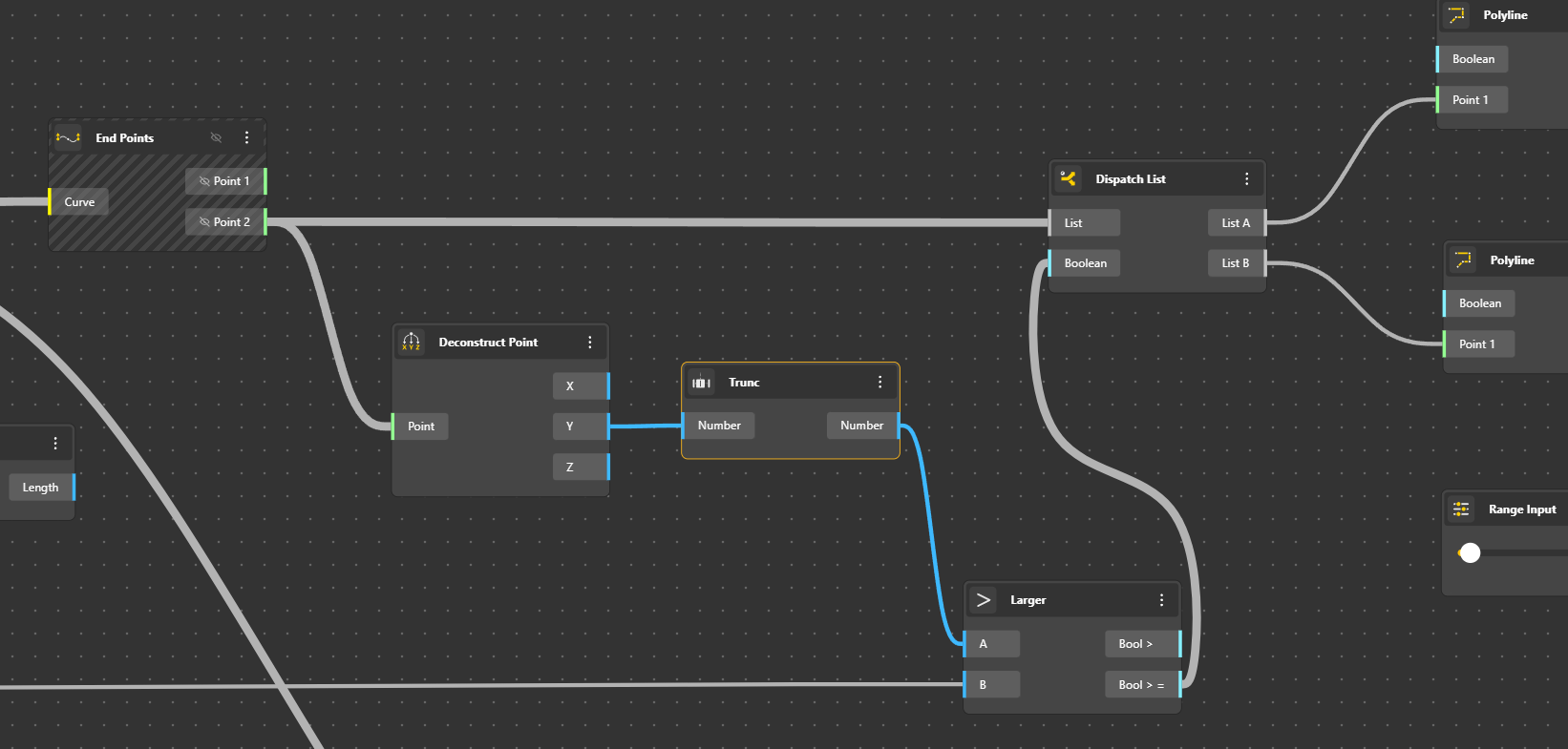
Nota : when a component is hatched, it means that elements are not visible. (Right Click Hide).
For the horizontal bars, the easiest way is to use the Pipe component with a Range Input to vary the Radius.
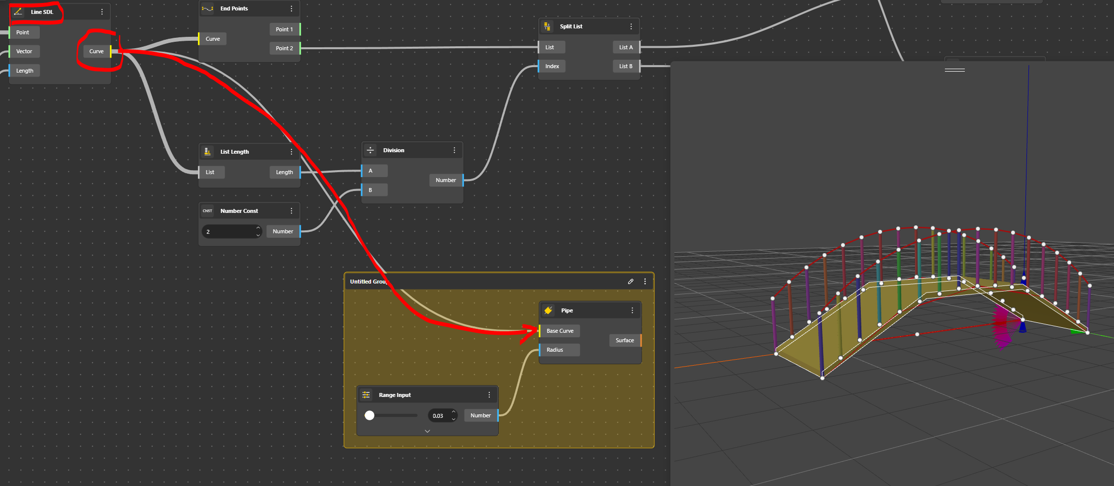
We try it for the hand railing.
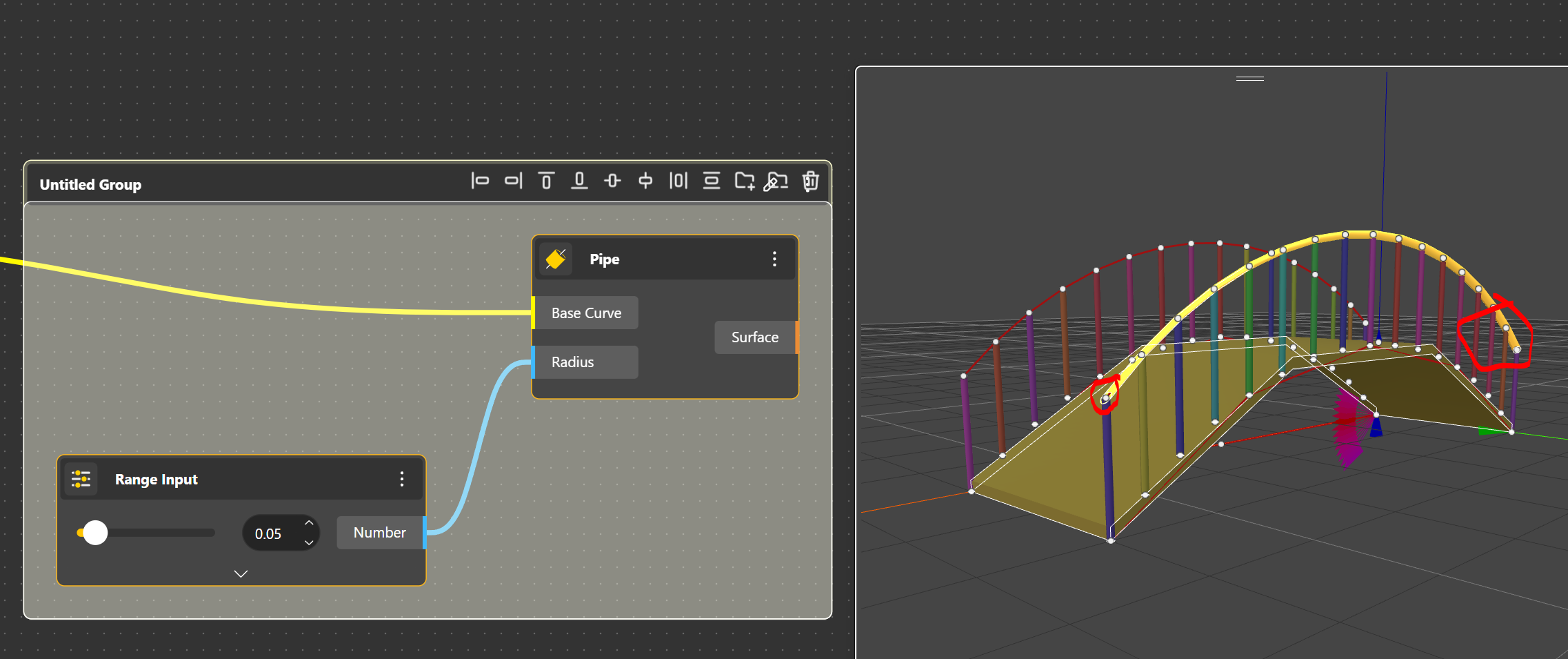
The Pipe doesn’t return a proper geometry with the hand railing. I believe it will be improved. We will use something else.
We extrude the curves in Z with Extrude Curve we indicate a Vector Z and and Range Input to vary the value.
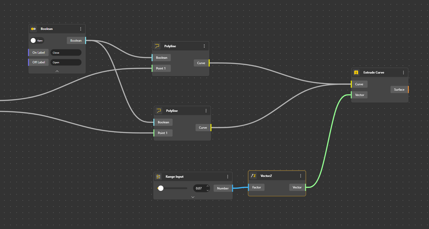
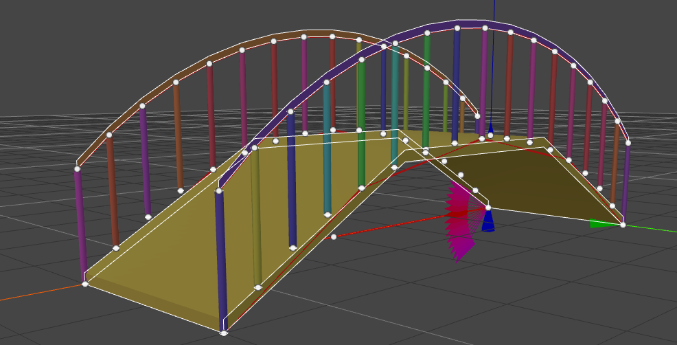
Ok, it’s done.
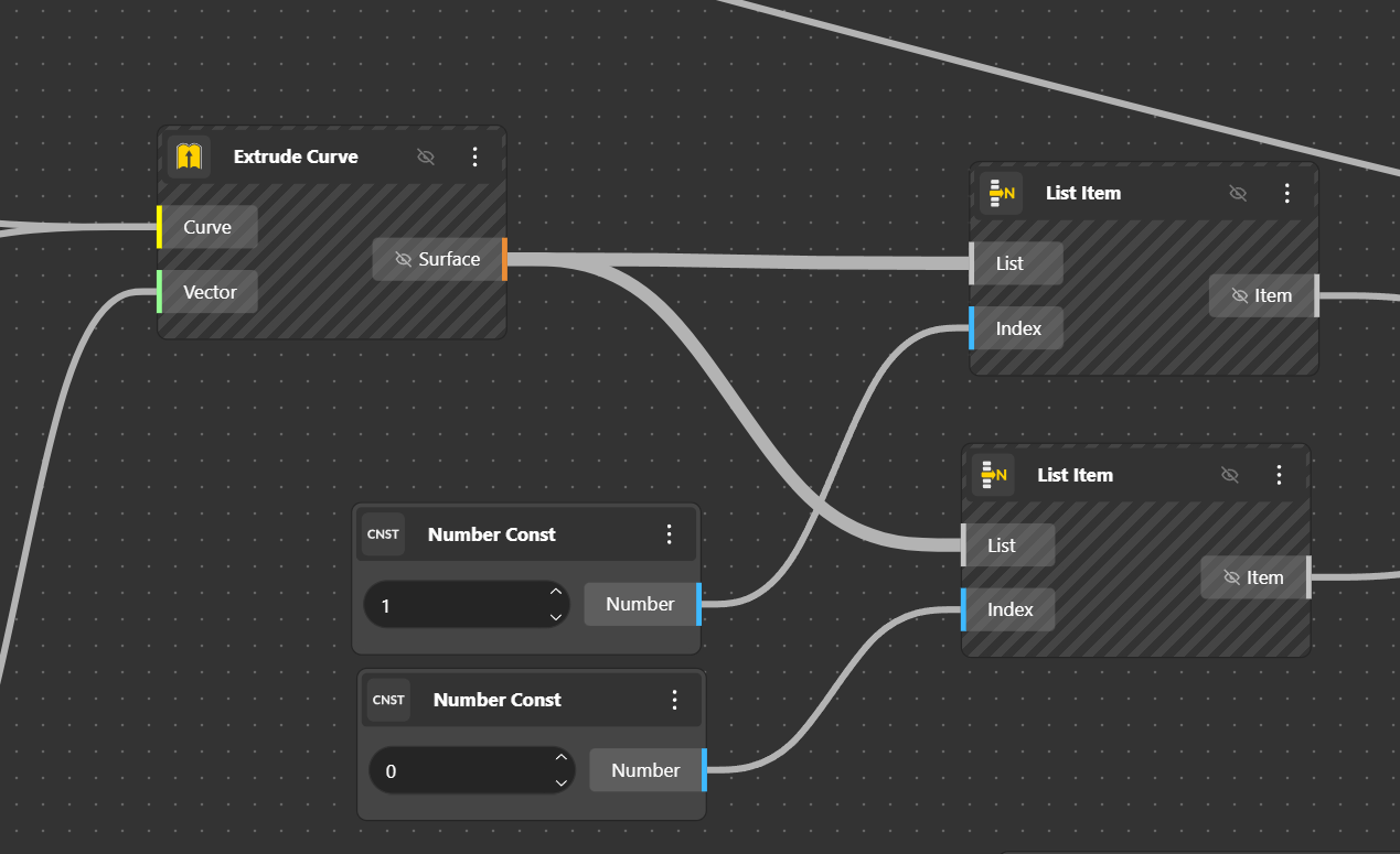
Then we separate the 2curves to extrude one in +Y and the other in –Y. To do that, we again cut the list into two parts. The two actual surfaces, those extruded in Z are in the same list with the value of 1 and 2 but in reality, they have the position 0 and 1. For somebody familiar with Grasshopper it’s obvious, there it’s a bit confusing.
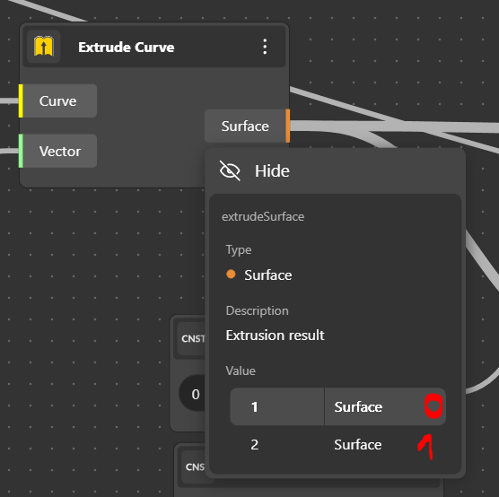
We separate our two extruded curves with a List Item component. Two in fact. For the first one the Index is 0 (position 0) and second one, the Index is 1 (position 1). As it has been said, it’s a bit confusing as unlike Grasshopper, the number of Items and the position can be confused. Unlike Grasshopper, it seems that it is not possible to have multiple Index or a -1.
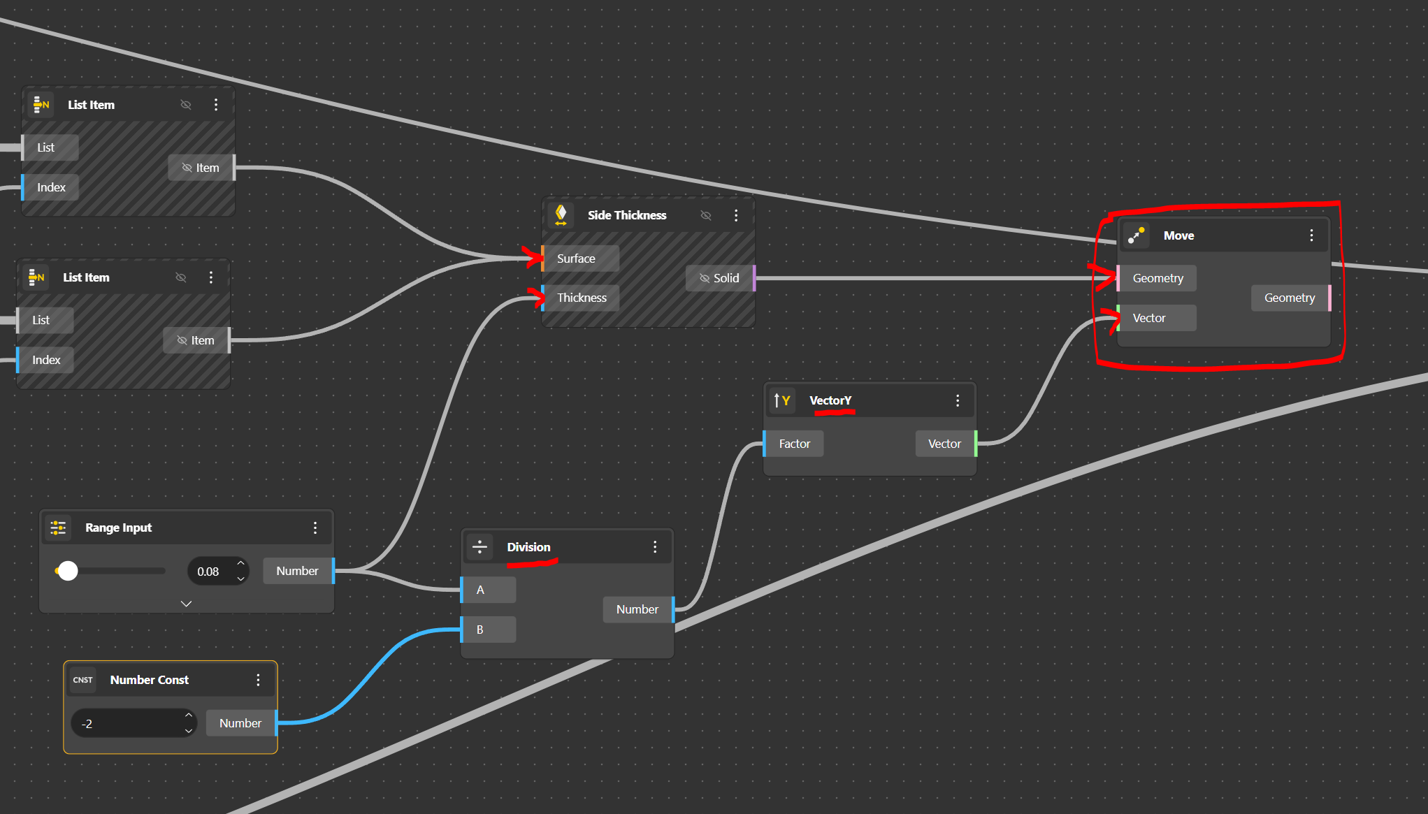
We will try something more straight forward using the Side Thickness component to add a width to our hand rails.
To finish, we will extrude the surfaces with a new component which is Side Thickness. We give a parametric value with the Range Input. Problem is, it is shifted and not aligned. For that we move this geometry in –Y at half of its width. Super easy, just Move the geometry, grab the thickness value divide it by -2. For that we need a Division component and a Number Const in which we input -2.
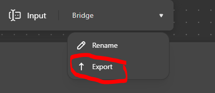
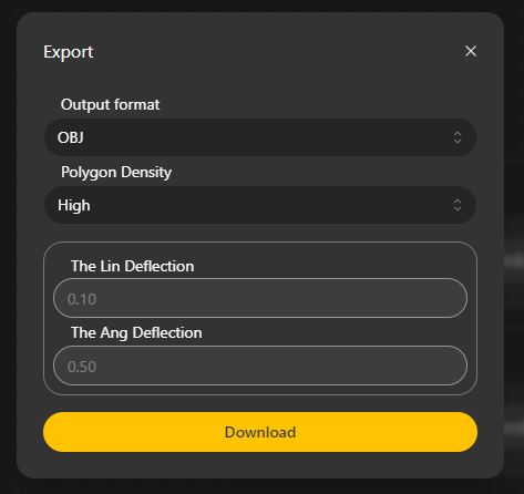
OBJ Export
To export, let’s bring all our 3D geometries to an exporter. But we might need a texture first. We get the Apply Material Component, we connect our geometry to Geometry. We can choose a colour with a Color Picker that will be connected to Color. We can play with Metallicity and/or Roughness with a Range Input, play with Opacity too if needed.
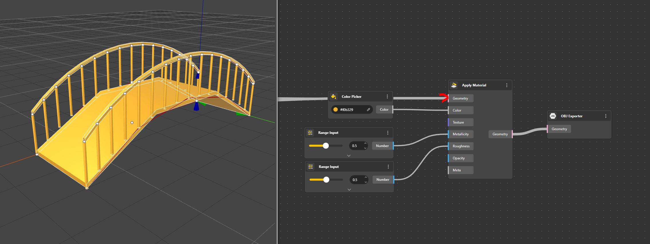
We export
Et voilà…
https://beegraphy.com/embed/64b0e990445210b8d1f74c02
Conclusion
Beegraphy, is a very promising solution for simple parametric designs. I see huge opportunities for teaching sessions and to easily discover the infinite possibilities of parametric design. As a Grasshopper power user, I can adapt fast. With a huge screen, Beegraphy is a must. This is a Beta version and I must say, I had some issues with Lists. I think it’s very much perfectible. Splitting a list, dispatching with Boolean returned me inexplicable results. Or I should more deeply understand the indexation logic. I’ll work on it. But all in all, I love this app, I will persist working with it.
(nota, native scale seems to be in millimetres. )