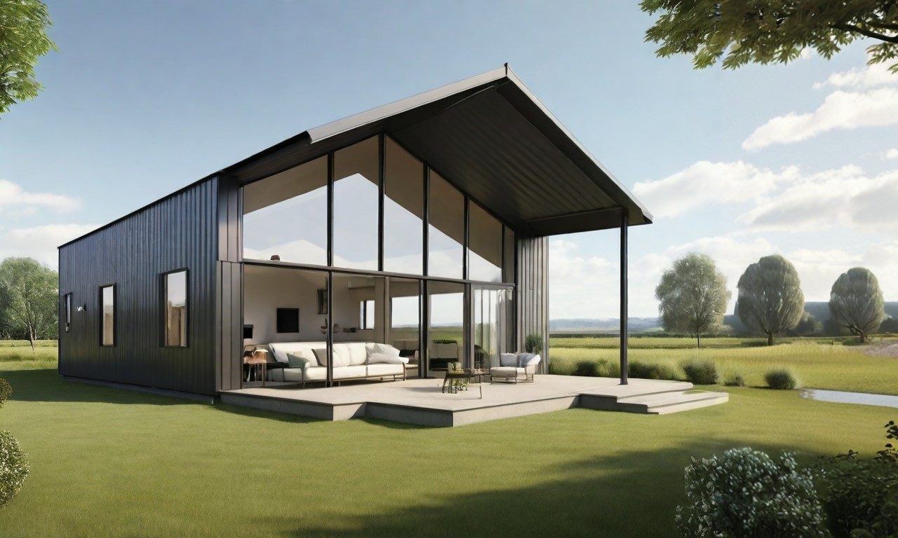
This tutorial aims to create a parametric structure, this structure shall be scaled in any direction.

We will use Beegraphy, the online Grasshopper for that. https://beegraphy.com/
BeeGraphy is an innovative cloud-based platform tailored for computational designers. It provides effortless cross-platform compatibility, removing the requirement for installations, thereby facilitating seamless usage on Windows, Mac, or Linux systems. By enabling model creation directly in the cloud and allowing easy sharing through a straightforward URL link, BeeGraphy fosters real-time collaboration and co-creation among individuals and teams. Beegraphy ensures that you can share your parametric models securely without disclosing the underlying script, empowering to present designs confidently. Additionally, Beegrapgy offers the opportunity to showcase and market models in Beegraphy online store, generating passive income.
Is this tutorial we will learn how to
- Create a basic parametric structure
- Using Lists and Lists Items
- Mirroring a geometry
Building the first Line
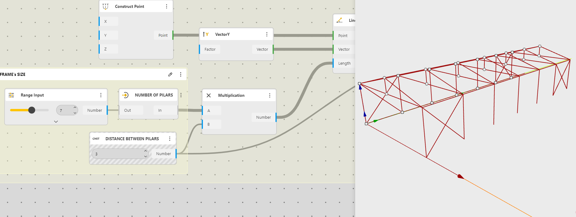
We will start with a first Line, it will be the Length of the building.
From a Construct Point, we create a Line SDL, a Vector is necessary to indicate the direction, the Length will be our building total Length.
Note, a In component will be often used to better visualize things. This component is neutral, it just takes the info in and out, and it can have it’s name changed.
This is how we can see our organization now. Remember the component’s name can be changed with a double click.
Building the frames
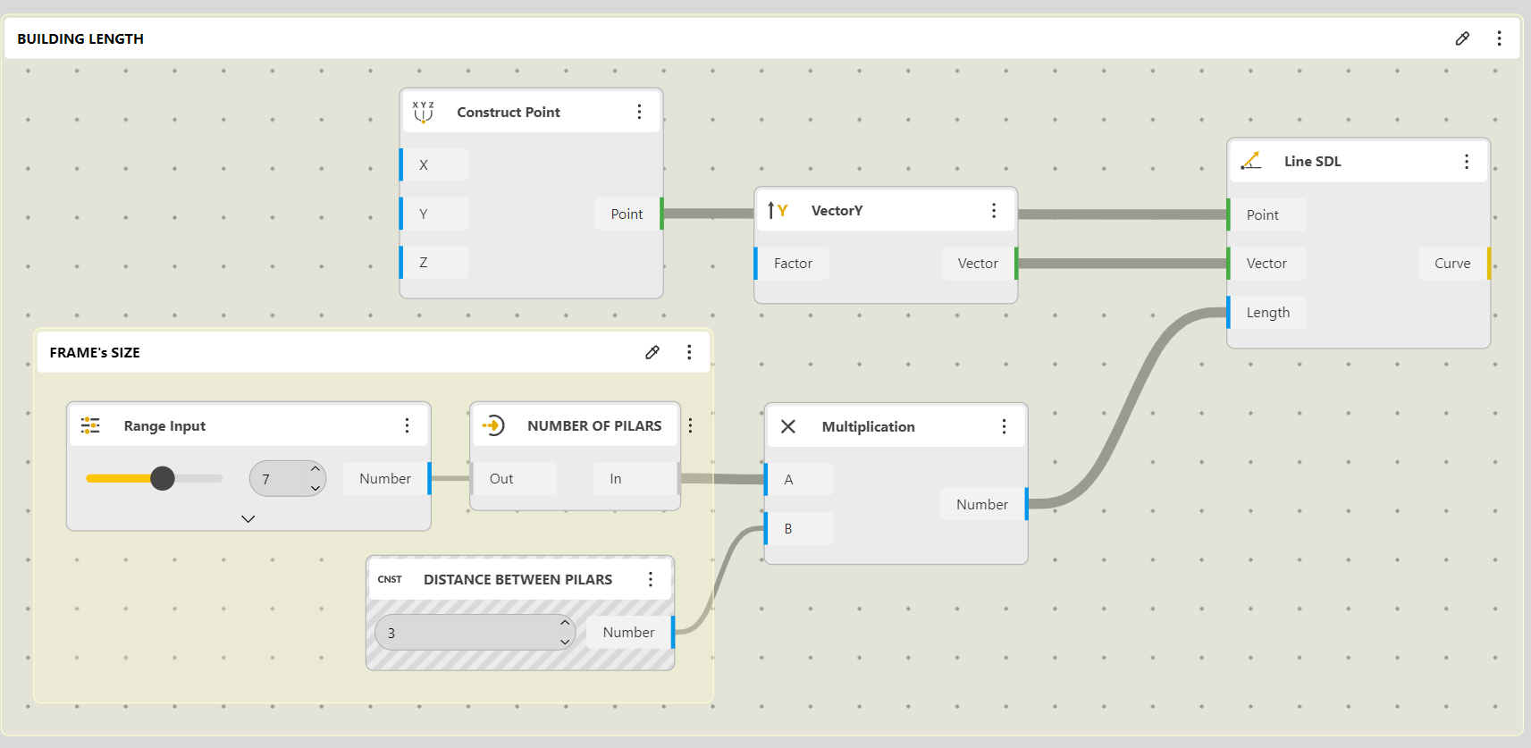
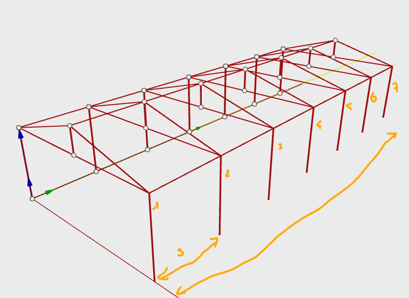
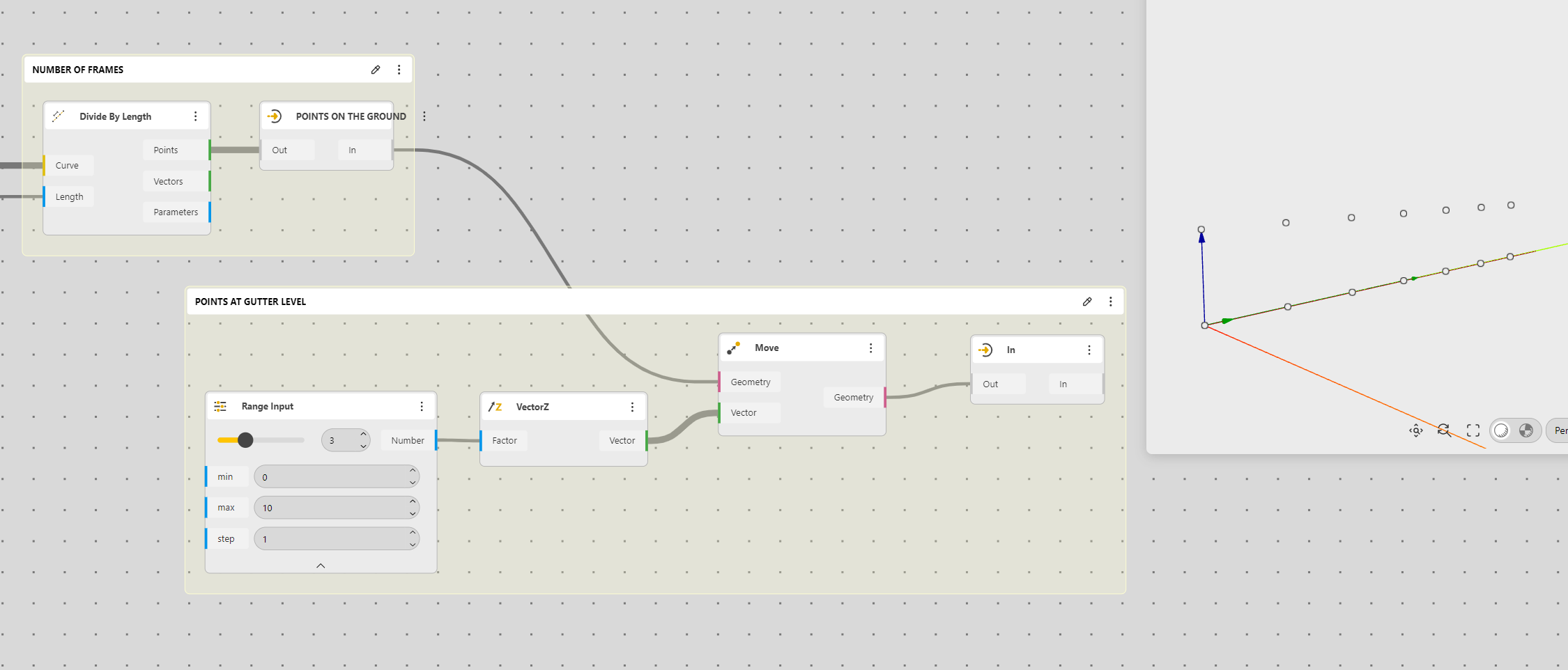
Now we divide our Curve, so we will a point avec 3 meters as we decided earlier.

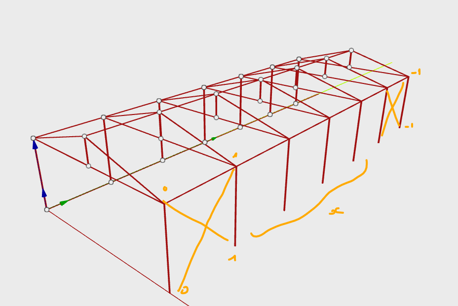
We now copy those points up to have the height of our building
We will have our points at the gutter level.
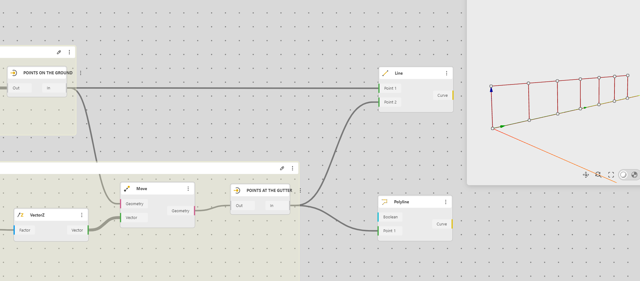
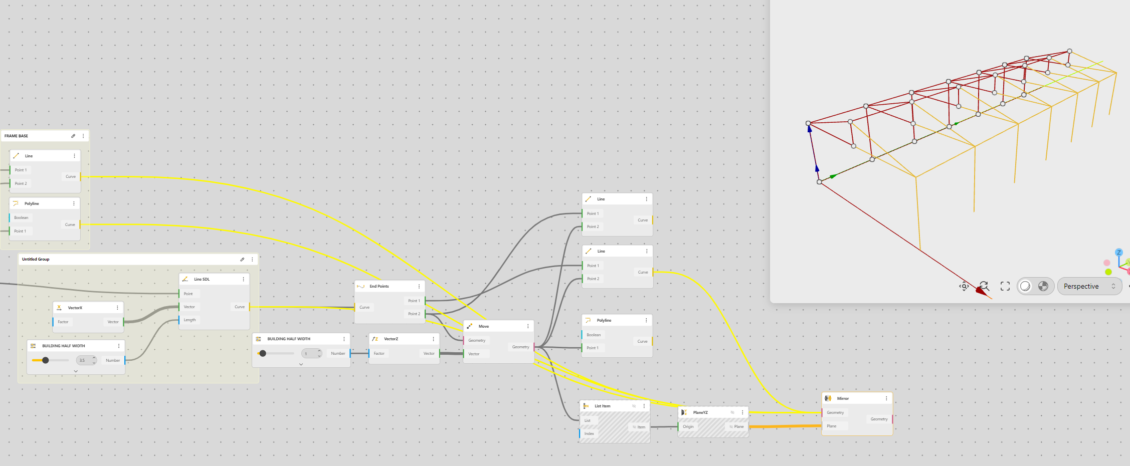
We can now connect the ground level points and the gutter level points to have our vertical frames, we can also add a Polyline at the gutter level to have the complete frame.
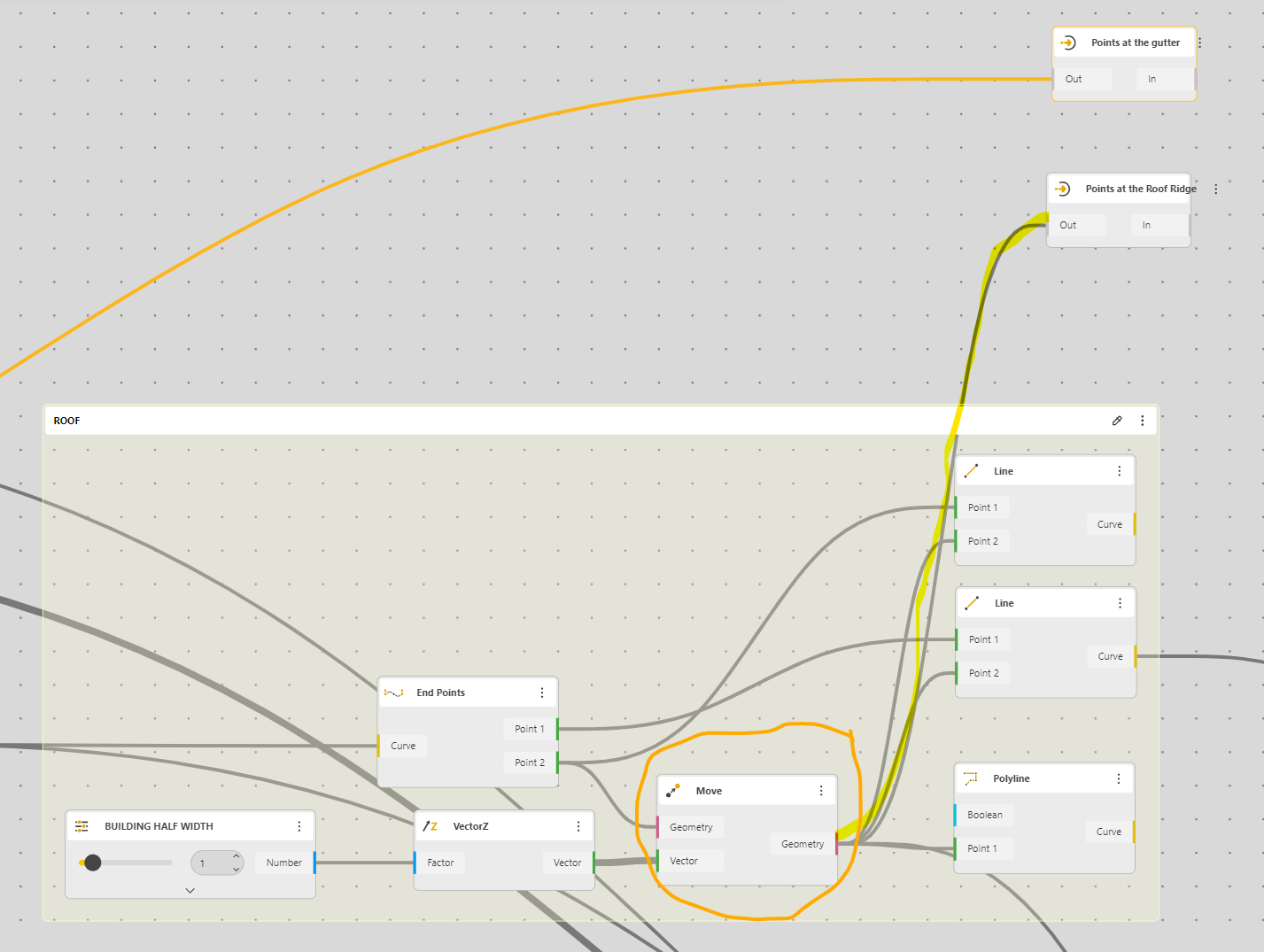
Roof
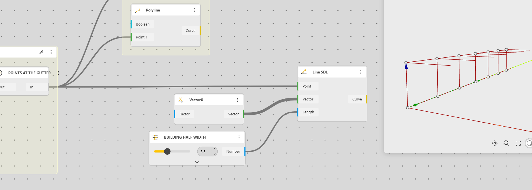
Now let’s add a pitched roof
As we are going to Mirror the structure, the best is to have a very simple approach in two times: length and height.
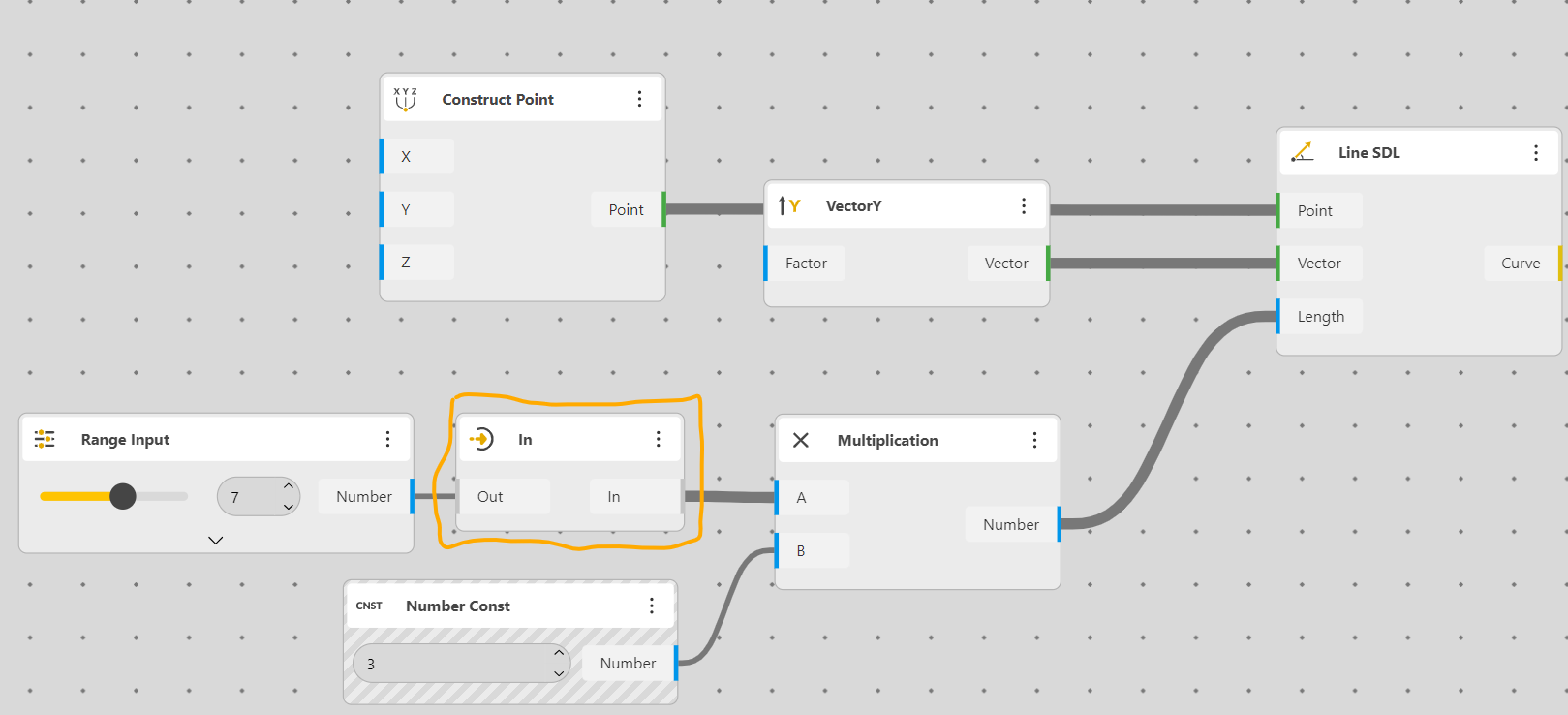
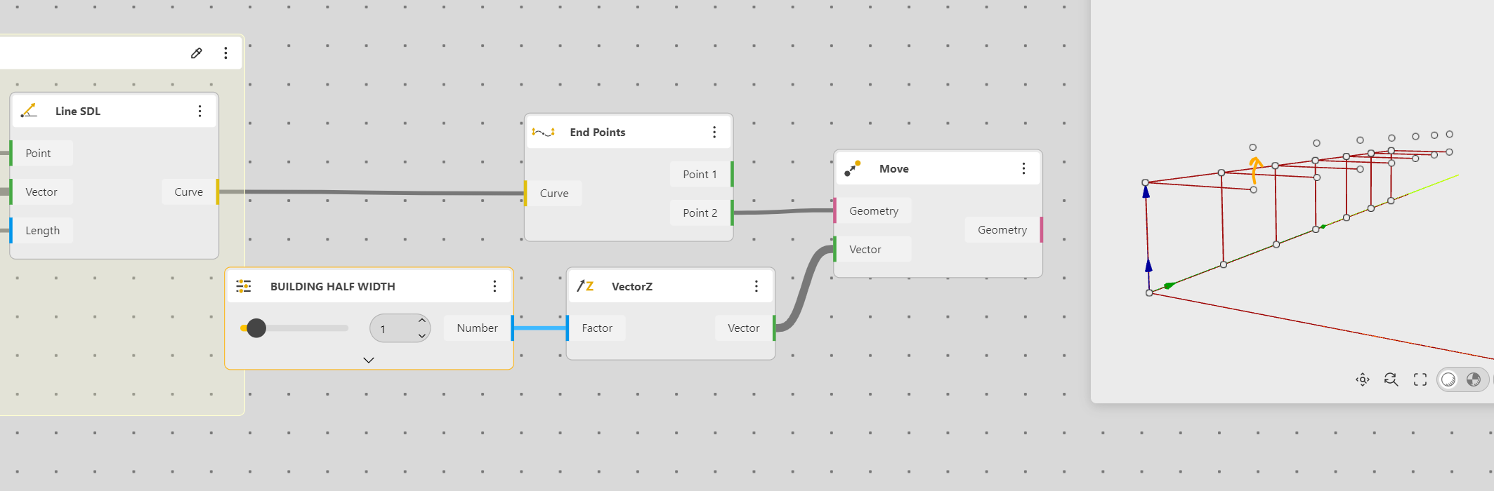
Length, let’s trace a Line SDL, a X Vector and a Range Input, to have the building’s half Width (because it will be mirrored). The range Output is renamed Half Width
We find the point at line’s End to elevate the extreme one at the required height.
For that we use a Curve end Points, then move up (Vector Z) with a value that will be given by the Range Value
Now we can finish connecting the points
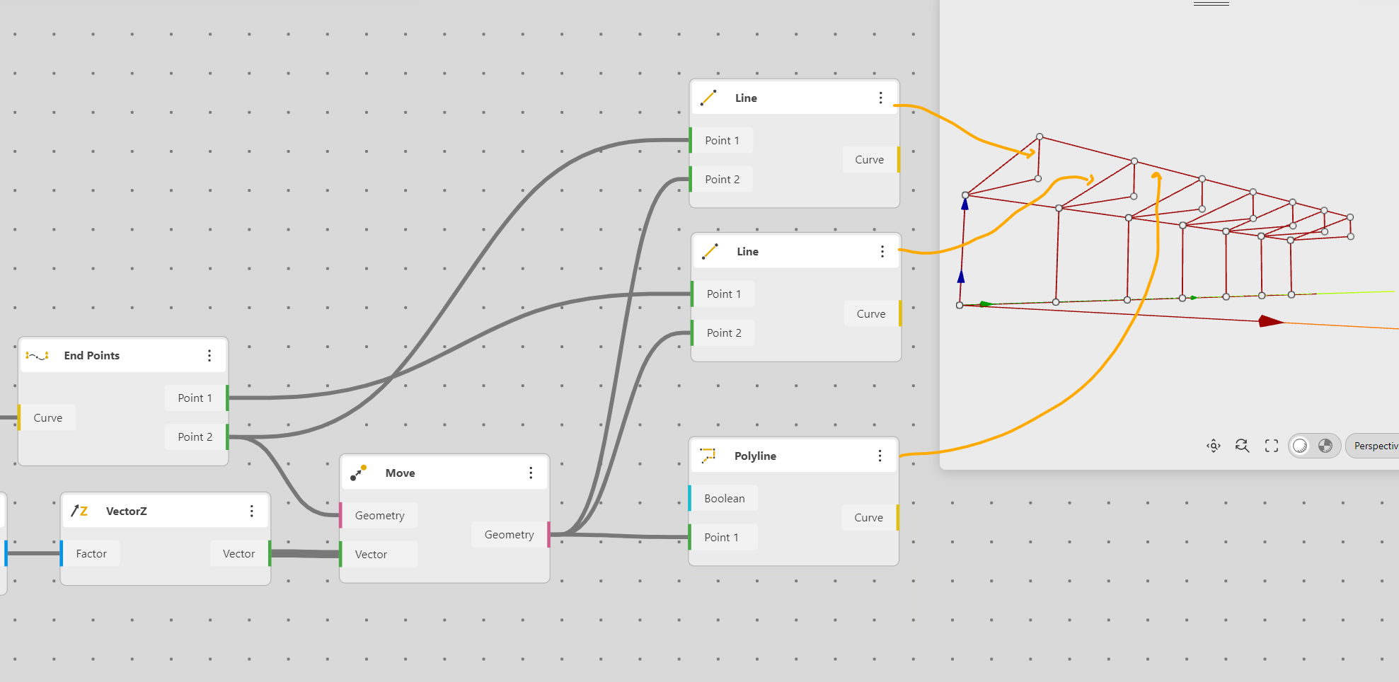
Ok, our frame in nearly complete, we can mirror it
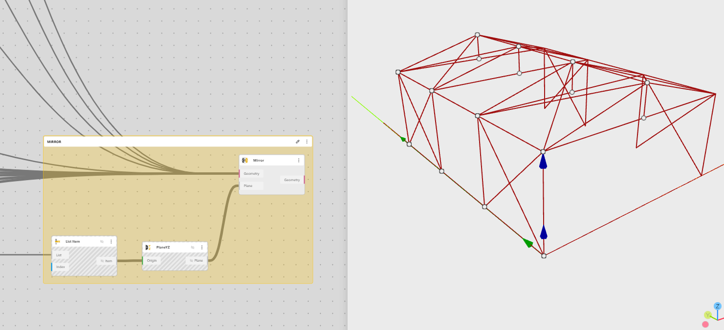
Mirroring
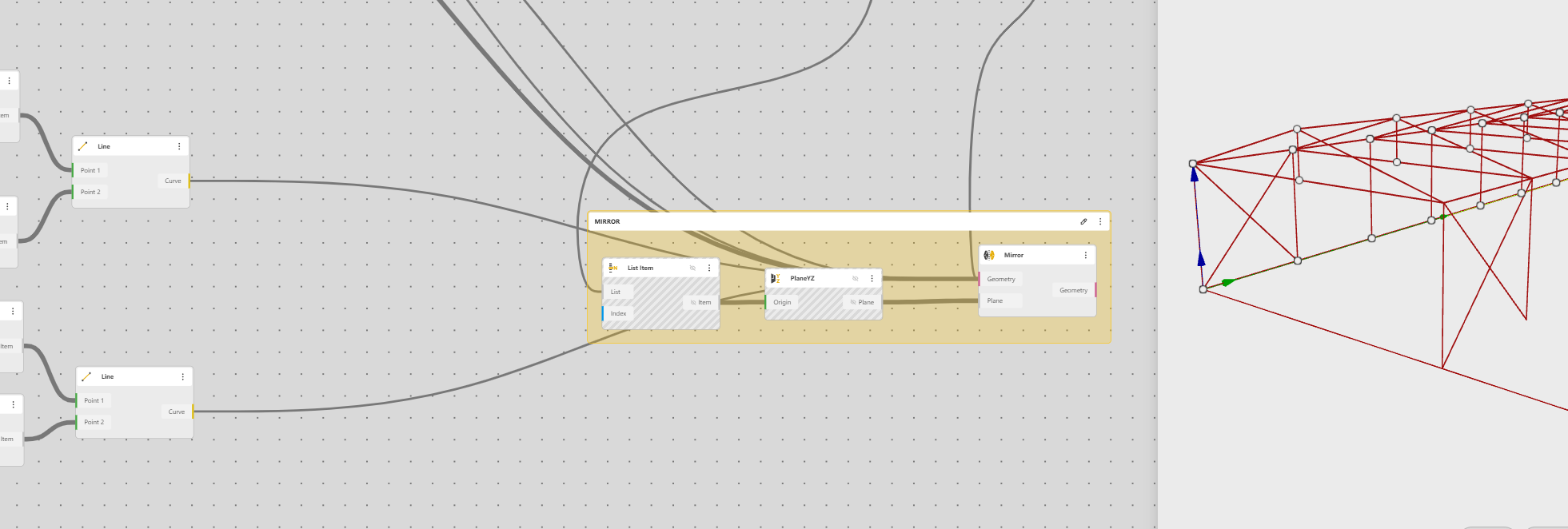
This is the setting.
A mirror need a Plan, we will choose a YZ plane and we fix it at the first point of the roof ridge. To do that we will use a List Item, by default the first Item is selected
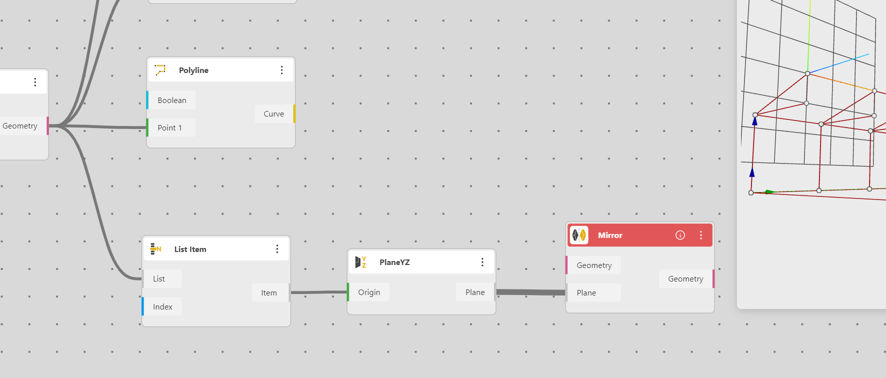
We now connect what we want to mirror
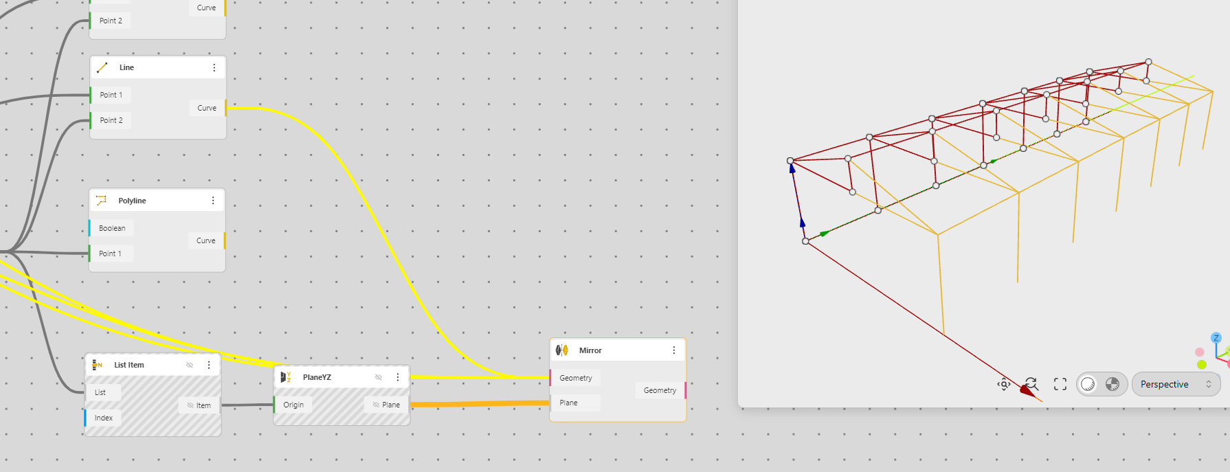
If we zoom back
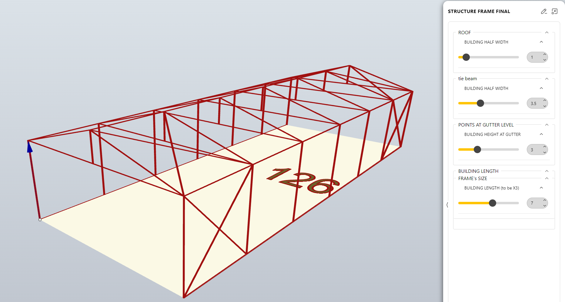
Ok, now we can play with the structure, it work to change all setting parametrically.
Ok but there is a “but”. Any engineer would say, “where are the bracings??”, How do want your structure to stand without bracings you foolish architects.
Bracings
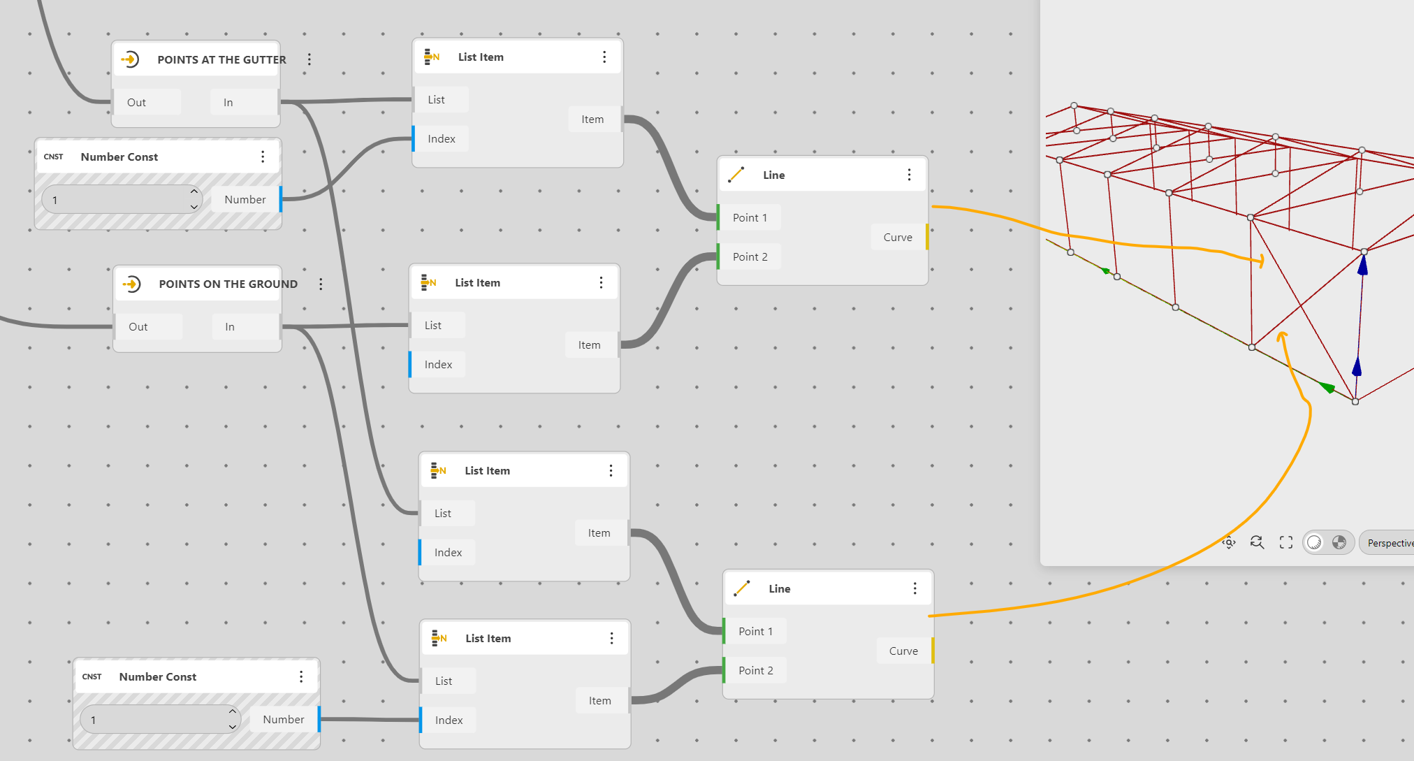
Creating the bracings is the the easiest part, it need a good understanding of lists;
So we need to connect Point 0 from the ground to point 1 to the gutter, and vice versa.
This will be easy. We will use In/Out components to have a better organization of our working space
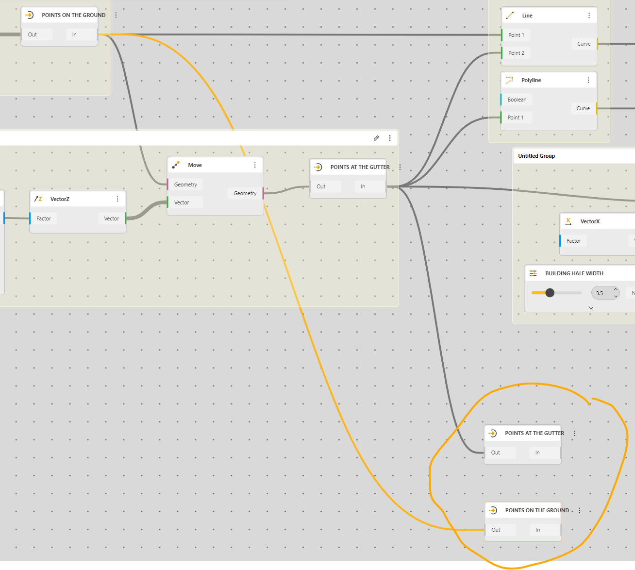
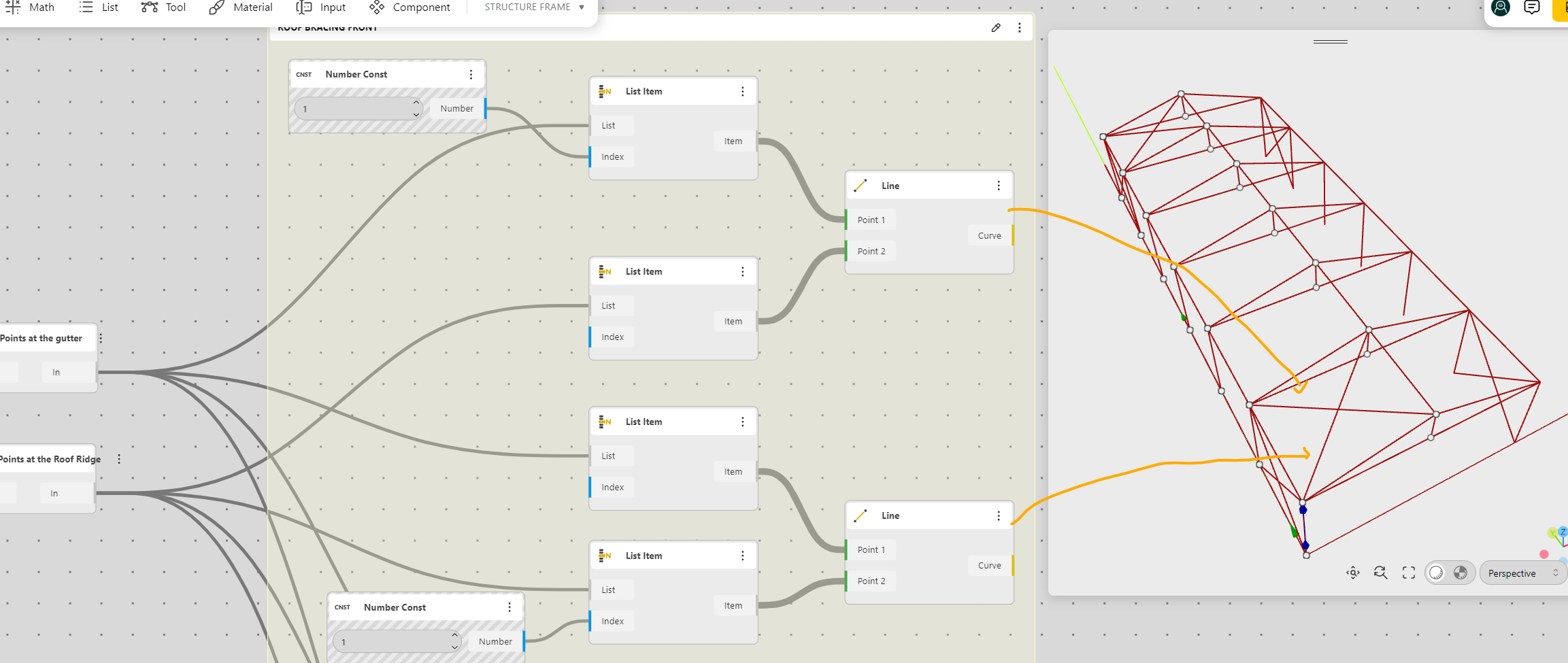
We use a List Item to select the first and second points
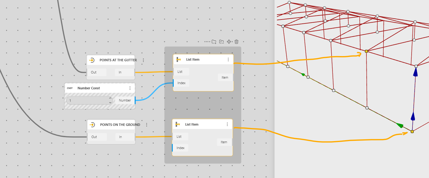
We connect with a Line 2 Points, and we do the same but we take the first in the gutter and the next on the ground
We can mirror those new lines,
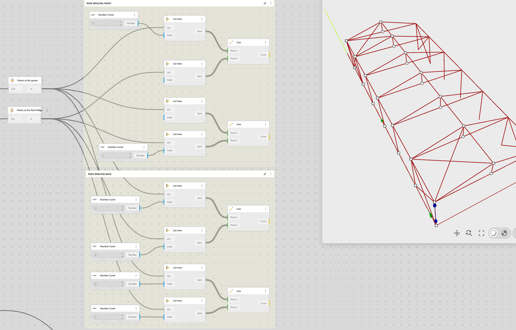
Now the bracing (which is not needed, at the very end of the structure. It is not needed for the structure to stand, but it’s needed to learn Lists!!
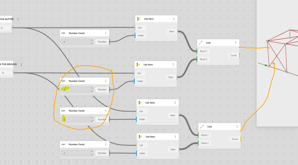
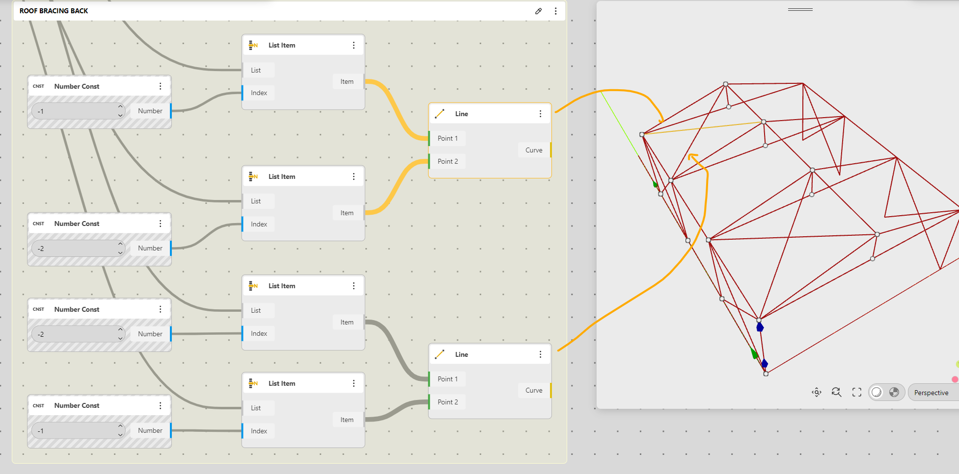
Bracings at the end of the structure
It will start the same
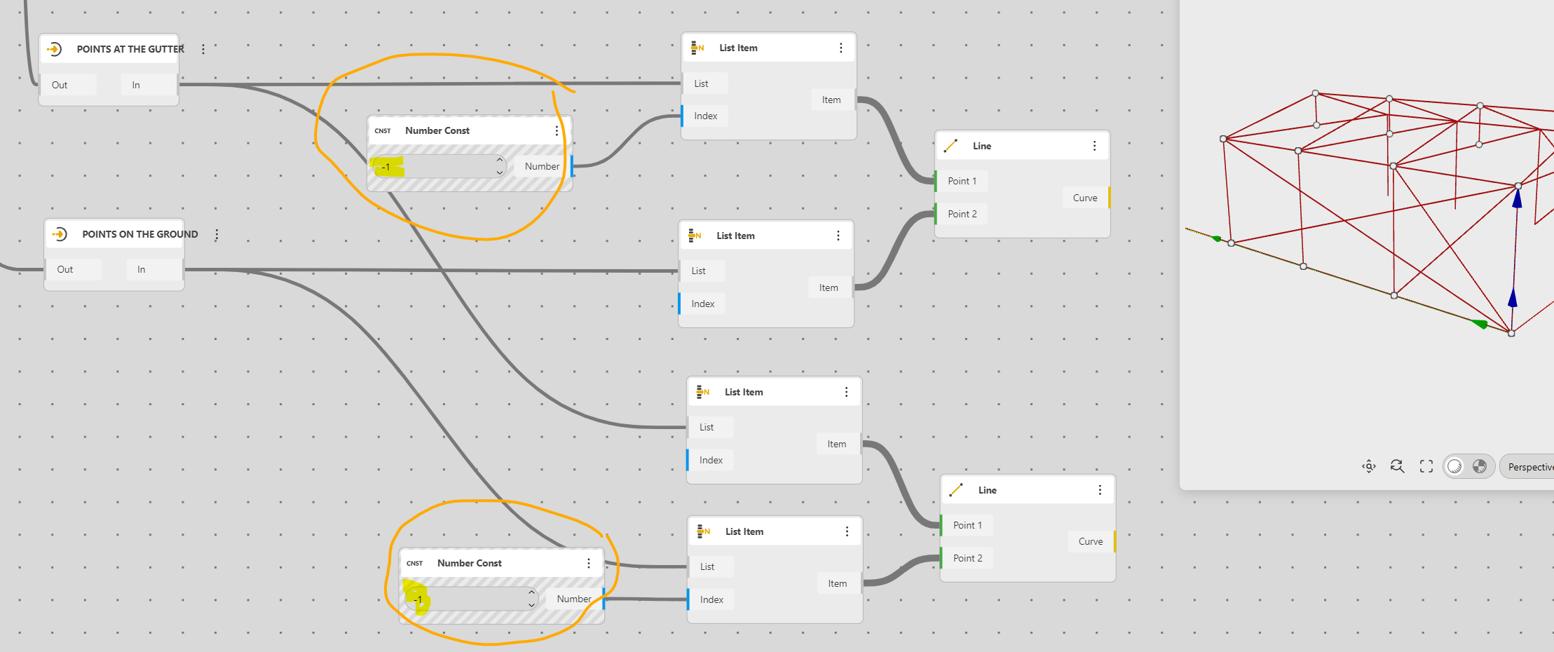
But instead of 1, we put -1, minus one means, the last one.
And -2 will be the one before the last !!!
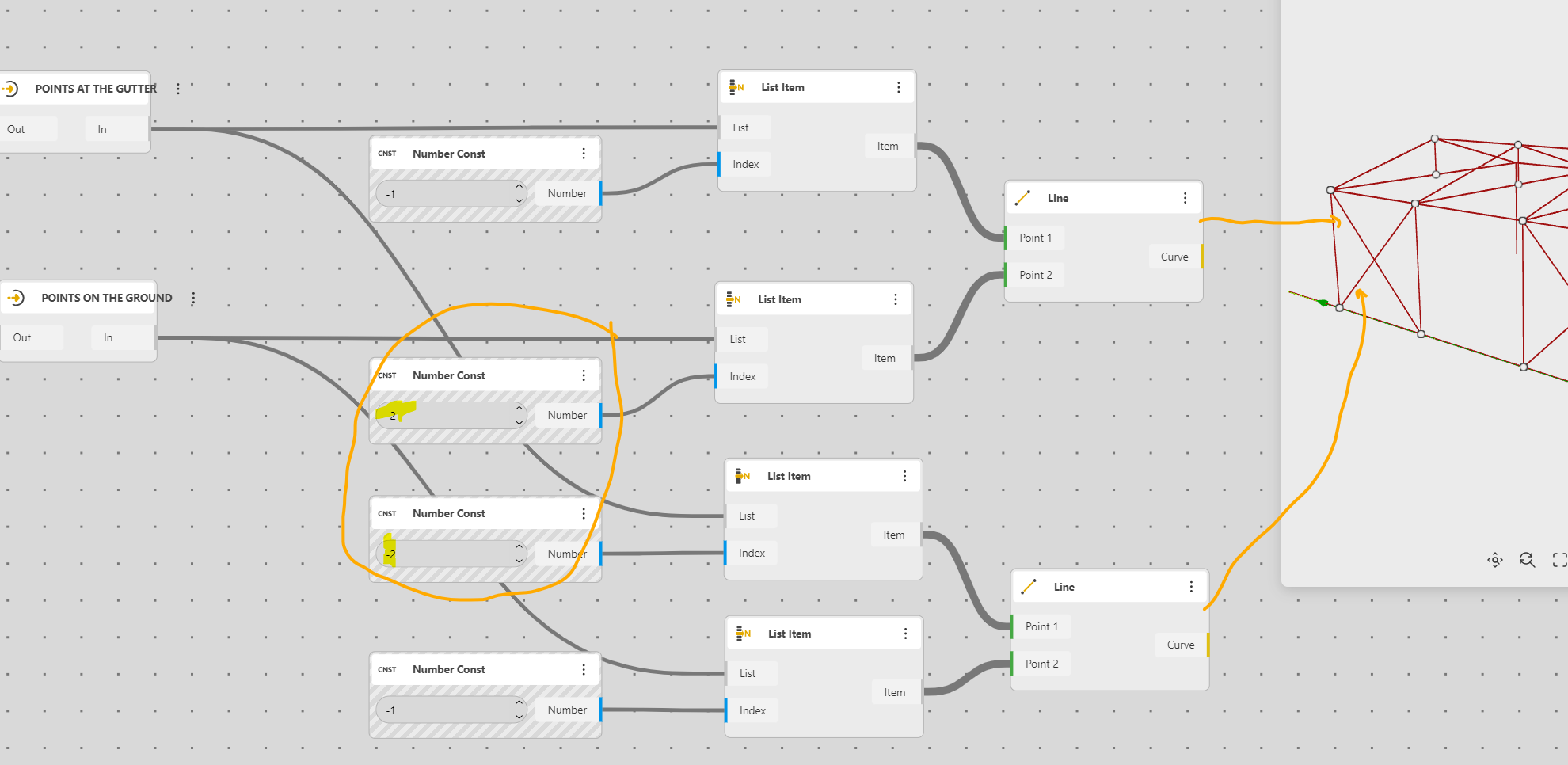
Let’s mirror and check if everything works
It does
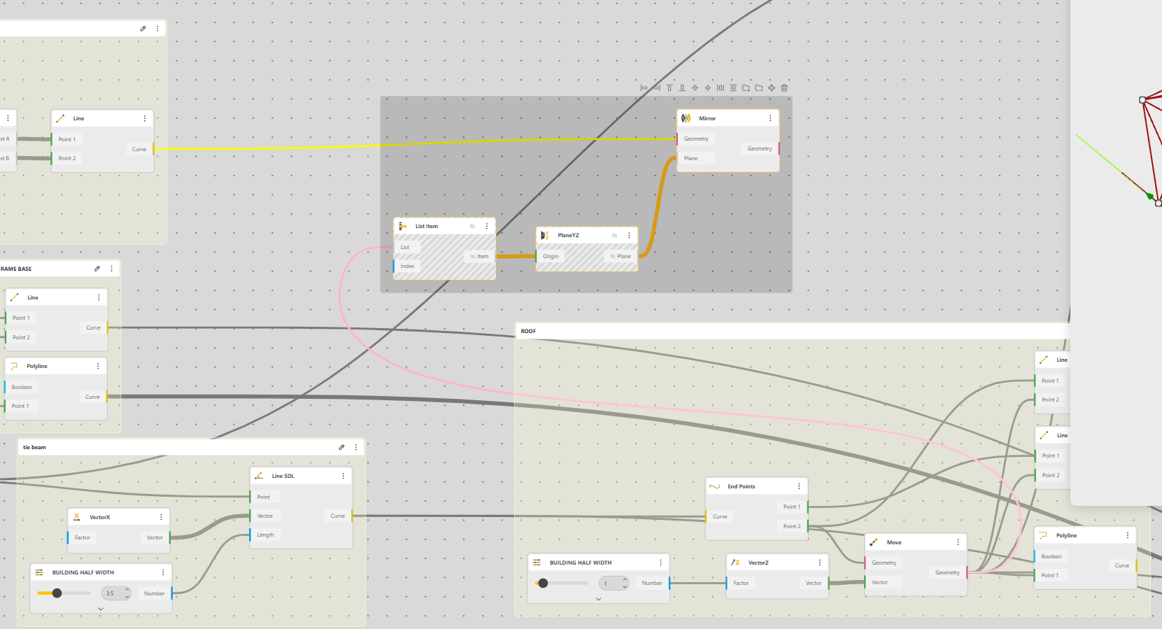
The roof also needs a bracing
It’s exactly the same procedure with the needed points
The one from the gutter and the ones from the roof ridge, we need to go back in the definition to find it.
Then, I’d say, it’s just a matter of copy/paste
Same way to do things, our engineers will be pleased
We mirror, clean, hide the unnecessary information and we’re good.
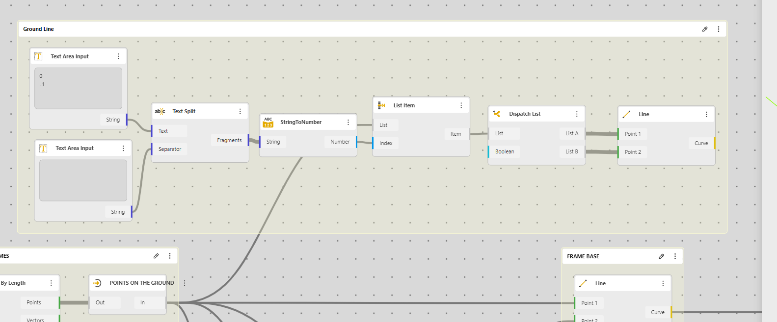
Getting the floor surface.
Before leaving, we’ll add a little bonus which is calculating the floor surface.
For that we need to create the floor
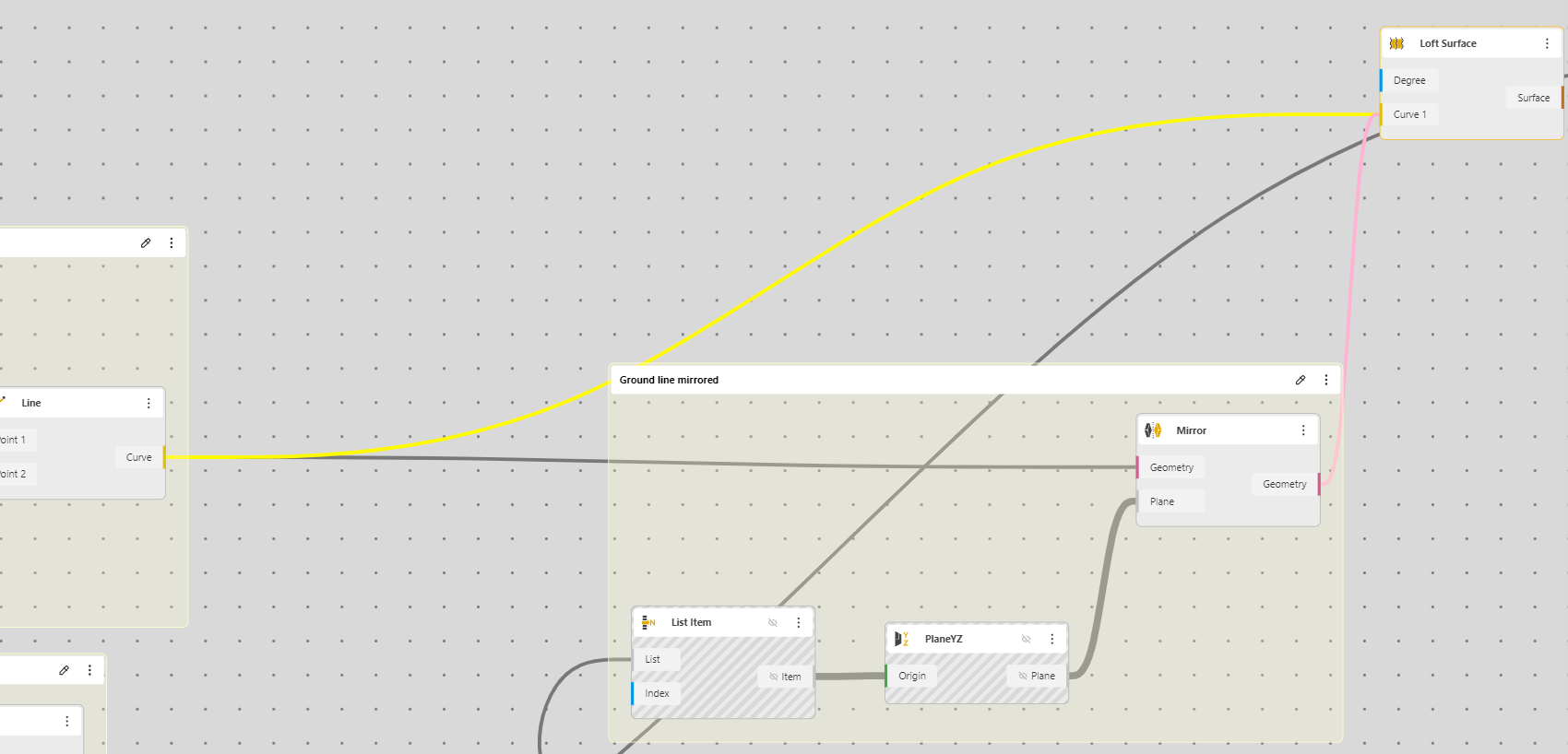
To have the first line on the ground we need the first and last points. That’s a bit tricky. For that we take a Text Area Input and we enter 0 and -1, then the text has to be split to appear as a list. (It’s easier in Grasshopper). So we add another text area Text Area Input and we just press enter inside. We connect everything as in the image, we then need to convert this text (even if it’s numbers) from String to Number. Then we dispatch to have our two points separately and then connect a Line….
Then we can Mirror this, we’ll use a different mirror with the same settings to have a better control.
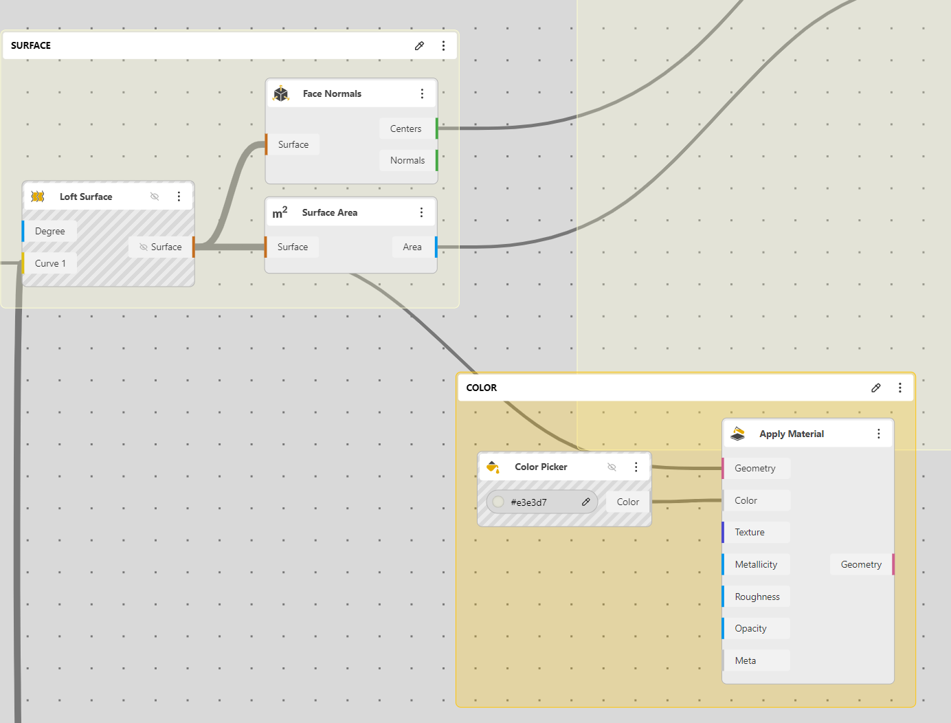
Then we can loft those two lines to have the surface
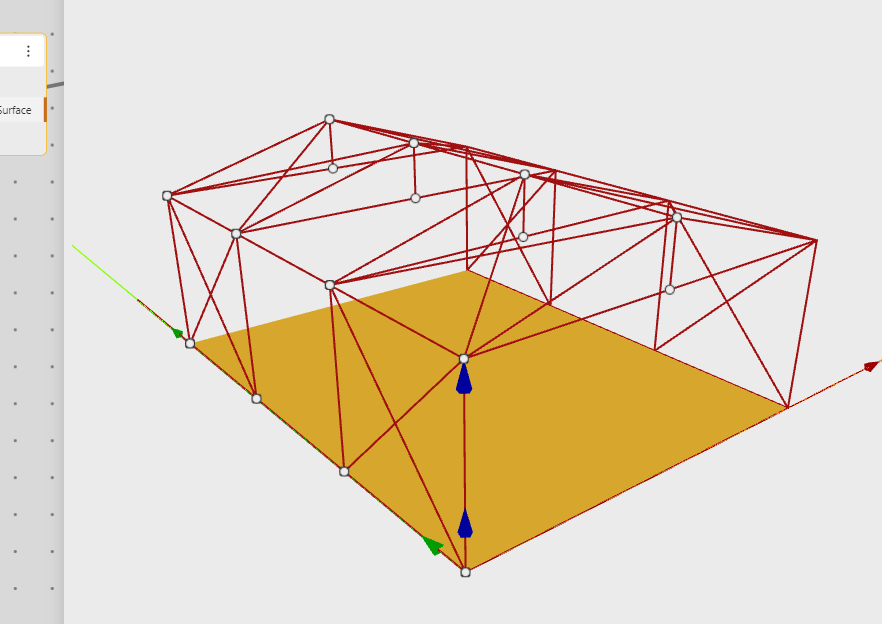
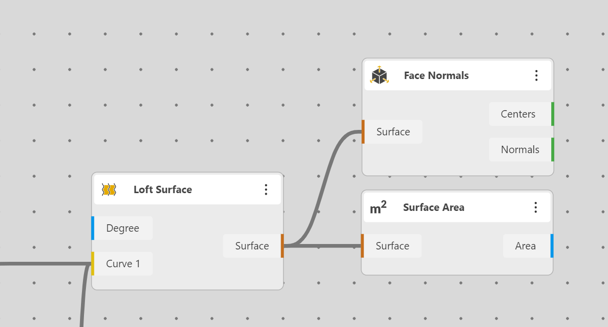
Then it’s the Surface component, we add a Face Normal to have a point where to put the text.
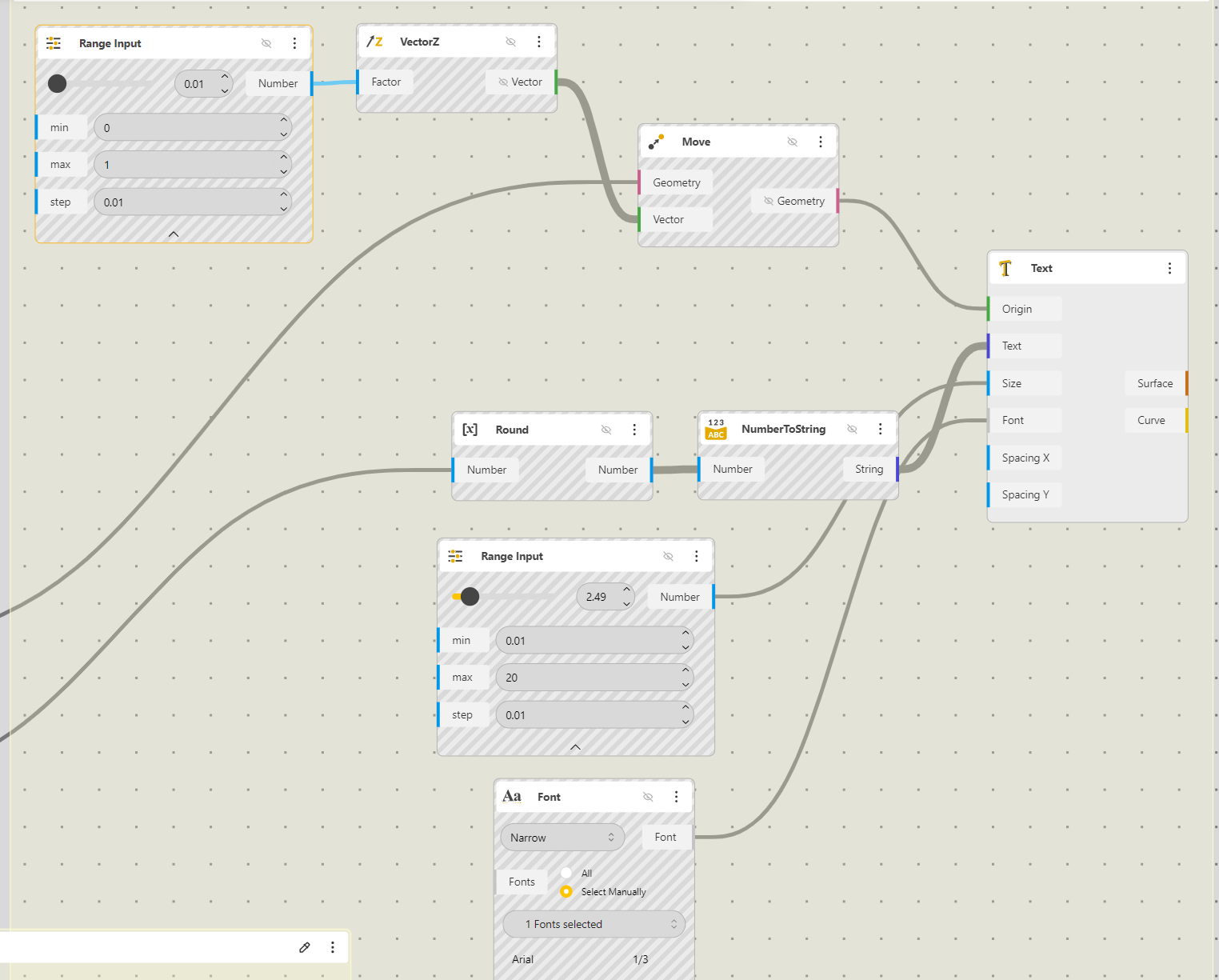
Let’s add the text, it’s now pretty standard
This is how to set things
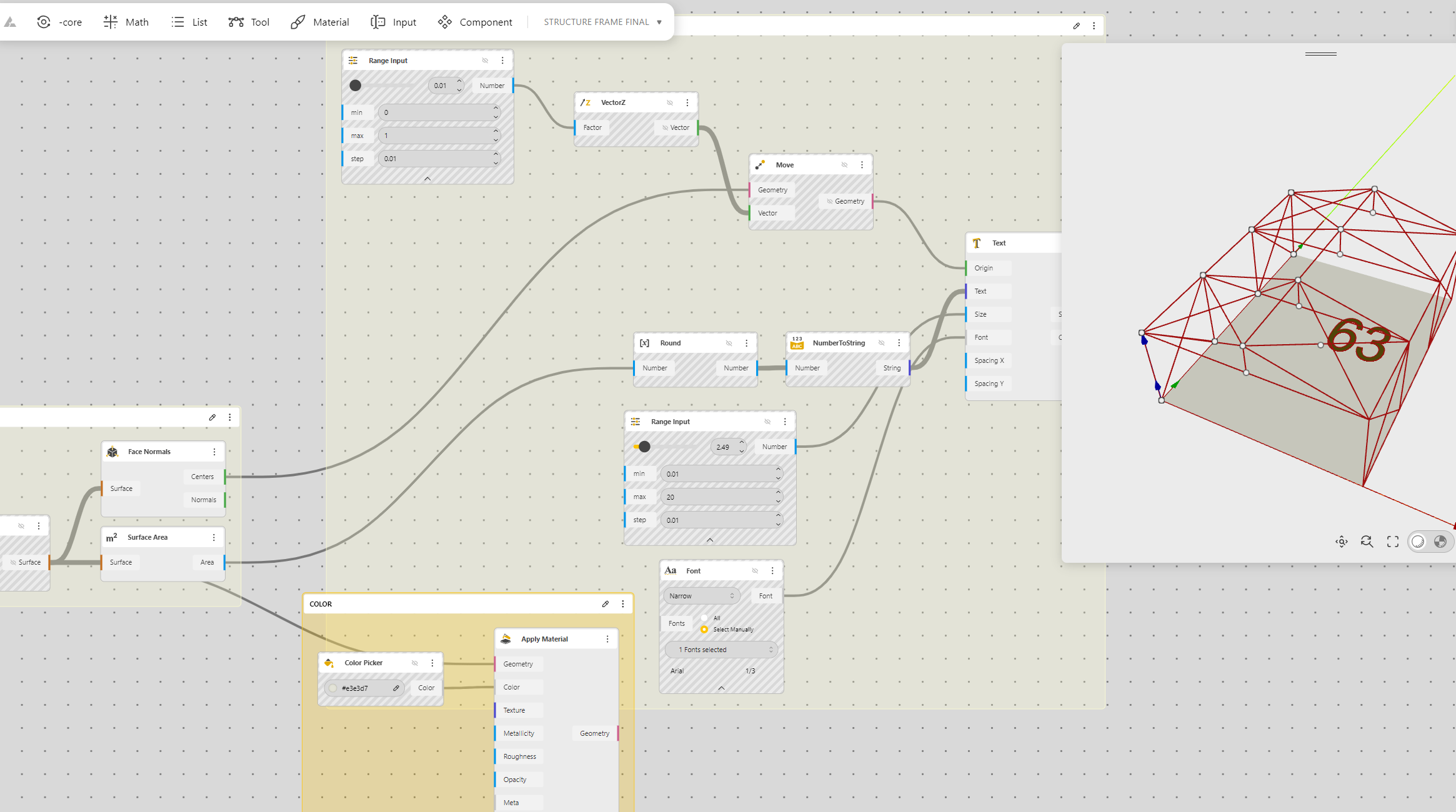
The color
The text is moved a bit up for a better vision.
That’s all
https://beegraphy.com/workspace/edit/65feb383de738b2132c65fe1
PLEASE FILL UP THE SURVEY, IT TAKE A FEW SECONDS ONY : HERE